A group of oxygen cutting processes that uses heat from an oxyfuel gas flame. See also OXYACETYLENE CUTTING, OXYHYDROGEN CUTTING, OXYNATURAL GAS CUTTING, and OXYPROPANE CUTTING.
Oxyfuel gas cutting (OFC) processes sever or remove metal by the chemical reaction of oxygen with the metal at elevated temperatures. The necessary tem-
perature is maintained by a flame of fuel gas burning in oxygen. In the case of oxidation resistant metals, the reaction is aided by adding chemical fluxes or metal powders to the cutting oxygen stream.
The process is known by various other names, such as burning, flame cutting, and flame machining. The actual cutting operation is performed by the oxygen stream. The oxygen-fuel gas flame is the mechanism used to raise the base metal to an acceptable preheat temperature range and to maintain the cutting operation.
The OFC torch is a versatile tool that can be readily taken to the work site. It is used to cut plates up to 2 m (7 ft) thick. Because the cutting oxygen jet has a 360” “cutting edge,” it provides a rapid means of cutting both straight edges and curved shapes to required dimensions without expensive handling equipment. The cutting direction can be continuously changed during operation.
Principles of Operation
The oxyfuel gas cutting process employs a torch with a tip (nozzle). The functions of the torch are to produce preheat flames by mixing the gas and the oxygen in the correct proportions, and to supply a concentrated stream of high-purity oxygen to the reaction
zone. The oxygen oxidizes hot metal and also blows the molten reaction products from the joint. The cutting torch mixes the fuel and oxygen for the preheating flames and aims the oxygen jet into the cut. The torch cutting tip contains a number of preheat flame ports
and a center passage for the cutting oxygen.
The preheat flames are used to heat the metal to a temperature where the metal will react with the cutting oxygen. The oxygen jet rapidly oxidizes most of the
metal in a narrow section to make the cut. Metal oxides and molten metal are expelled from the cut by the kinetic energy of the oxygen stream. Moving the torch across the workpiece at a specified rate produces a continuous cutting action. The torch may be moved manually or by a mechanized carriage.
The accuracy of a manual operation depends largely on the skill of the operator. Mechanized operation generally improves the accuracy and speed of the cut and the finish of the cut surfaces.
Kerf. When a piece is cut by an OFC process, a narrow width of metal is progressively removed. The width of the cut is called a kel3F, as shown in Figure 0-4. Control of the kerf is important in cutting operations where dimensional accuracy of the part and
squareness of the cut edges are significant factors in quality control. With the OFC process, kerf width is a function of the size of tip used, speed of cutting, and flow rates of cutting oxygen and preheating gases. As material thickness increases, oxygen flow rates must usually be increased. Cutting tips with larger cutting oxygen ports are required to handle the higher flow rates. Consequently, the width of the kerf increases as the material thickness being cut increases.
Kerf width is especially important in shape cutting. Compensation must be made for kerf width in the layout of the work, or the design of the template. Generally, on materials up to 50 mm (2 in.) thick, kerf width can be maintained within +0.4 mm (+1/64 in.).
Drag. When the speed of the cutting torch is adjusted so that the oxygen stream enters the top of the kerf and exits from the bottom of the kerf along the axis of the tip, the cut will have zero drag. If the speed of cutting is increased, or if the oxygen flow is decreased, the oxygen available in the lower regions of the cut decreases. With less oxygen available, the oxidation reaction rate decreases, and also the oxygen jet has less energy to carry the reaction products out of the kerf. As a result, the most distant part of the cutting stream lags behind the portion nearest to the torch tip. The length of this lag, measured along the line of cut, is referred to as the drug. This is shown in Figure 0-4.
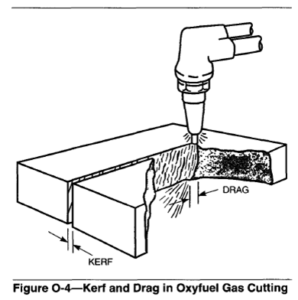
Drag may also be expressed as a percentage of the cut thickness. A 10% drag means that the far side of the cut lags the near side of the cut by a distance equal to 10%of the material thickness.
An increase in cutting speed with no increase in oxygen flow usually results in a larger drag. This may cause a decrease in cut quality. There is also a strong possibility of loss of cut at excessive speeds. Reverse drag may occur when the cutting oxygen flow is too high or the travel speed is too low. Under these conditions, poor quality cuts usually result. Cutting stream lag caused by incorrect torch alignment is not considered to be drag.
Cutting speeds below those recommended for best quality cuts usually result in irregularities in the kerf. The oxygen stream inconsistently oxidizes and washes away additional material from each side of the cut. Excessive preheat flame results in undesirable melting and widening of the kerf at the top.
Chemistry of Oxyfuel Gas Cutting
The process of oxygen cutting is based on the characteristic of high-purity oxygen to combine rapidly with iron when it is heated to its ignition temperature, above 870°C (1600°F). The iron is rapidly oxidized by the high-purity oxygen and heat is liberated by several reactions.
The balanced chemical equations for these reactions are the following:
(1) Fe + 0+FeO + heat (267 kl), first reaction
(2) 3Fe + 202 + Fe304 + heat (1120 kJ) second reaction
(3) 2Fe + 1.5 O2 +Fe203+ heat (825 kJ), third reaction
The tremendous heat release of the second reaction predominates over that of the first reaction, which is supplementary in most cutting applications. The third reaction occurs to some extent in heavier cutting appli- cations. Stoichiometrically, 2.9 m3 (104 ft3) of oxygen will oxidize 1 kg (2.2 lb) of iron to Fe304.
In actual operations, the consumption of cutting oxygen per unit mass of iron varies with the thickness of the metal. Oxygen consumption per unit mass is higher than the ideal stoichiometric reaction for thicknesses less than approximately 40 mm (1-1/2 in.), and it is lower for greater thicknesses. For thicker sections, the oxygen consumption is lower than the ideal stoichiometric reaction because only part of the iron is completely oxidized to Fe304. Some oxidized or partly oxidized iron is removed by the kinetic energy of the rapidly moving oxygen stream.
Chemical analysis has shown that, in some instances, over 30% of the slag is unoxidized metal. The heat generated by the rapid oxidation of iron melts some of the iron adjacent to the reaction surface. This molten iron is swept away with the iron oxide by the force of the oxygen stream. The concurrent oxidizing reaction heats the layer of iron at the active cutting front.
The heat generated by the iron-oxygen reaction at the focal point of the cutting reaction (the hot spot) must be sufficient to continuously preheat the material to the ignition temperature. Allowing for the loss of heat by radiation and conduction, there is ample heat to sustain the reaction. In actual practice, the top surface of the material is frequently covered by mill scale or rust. That layer must be melted away by the preheat flames to expose a clean metal surface to the oxygen stream. Preheat flames help to sustain the cutting reaction by providing heat to the surface. They also shield the oxygen stream from turbulent interaction with air.
The alloying elements normally found in carbon steels are oxidized or dissolved in the slag without markedly interfering with the cutting process. When alloying elements are present in steel in appreciable amounts, their effect on the cutting process must be
considered. Steels containing minor additions of oxidation resistant elements, such as nickel and chromium, can still be oxygen-cut. However, when oxidation resistant elements are present in large quantities, modifications to the cutting technique are
required to sustain the cutting action. This is true for stainless steels.
Oxygen. Oxygen used for cutting operations should have a purity of 99.5% or higher. Lower purity reduces the efficiency of the cutting operation. A 1% decrease in oxygen purity to 98.5% will result in a decrease in cutting speed of approximately 15%, and an increase of about 25% in consumption of cutting oxygen. The quality of the cut will be impaired, and the amount and tenacity of the adhering slag will increase. With oxygen purity below 95%, the familiar cutting action disappears, and it becomes a melt-and-wash action that is usually unacceptable.
Preheating Fuels. Functions of the preheat flames in the cutting operation are the following:
(1) Raise the temperature of the steel to the ignition point
(2) Add heat energy to the work to maintain the cutting reaction
(3)Provide a protective shield between the cutting oxygen stream and the atmosphere
(4)Dislodge from the upper surface of the steel any rust, scale, paint, or other foreign substance that would stop or retard the normal forward progress of the cutting action
A preheat intensity that rapidly raises the steel to the ignition temperature will usually be adequate to maintain cutting action at high travel speeds. However, the quality of the cut will not be the best. High-quality cutting can be carried out at considerably
lower preheat intensities than those normally required for rapid heating. On most larger cutting machines, dual range gas controls are provided that limit high intensity preheating to the starting operation. Then the preheat flames are reduced to lower intensity during
the cutting operation, to save fuel and oxygen and to provide a better cut surface.
A number of commercially available fuel gases are used with oxygen to provide the preheating flames. Some have proprietary compositions. Fuel gases are generally selected because of availability and cost. Properties of some commonly used fuel gases are listed in Table 0-2. To understand the significance of the information in this table, it is necessary to understand some of the terms and concepts involved in the burning of fuel gas. See OXYFUEL GAS WELDING.
Fuel Selection
Combustion intensity or specific flame output for various fuel gases are important considerations in fuel gas selection. Some of the more common fuel gases used are: acetylene, natural gas, propane, hydrogen, propylene and methyl-acetylene propadiene.
Some of the factors to be considered when selecting a particular fuel gas are:
(1)The time required for preheating when starting cuts on square edges and rounded corners and also when piercing holes for cut starts.
(2) The effect on cutting speeds
(3)The effect on productivity
(4) The cost and availability of the fuel gases
(5) Volume of oxygen required per volume of fuel gas to obtain a neutral flame
(6) Safety in transporting and handling of gases
For best performance and safety, the torches and tips should be designed for the particular fuel selected. Acetylene.Acetylene is widely used as a fuel gas for oxygen cutting and also for welding. Its chief advan- tages are availability, high flame temperature, and widespread familiarity with its flame characteristics among users.
Combustion of acetylene with oxygen produces a hot, short flame with a bright inner cone at each pre- heat port. The hottest point is at the end of this inner cone. Combustion is completed in the long outer flame. The sharp distinction between the two flames helps to adjust the oxygen-to-acetylene ratio for the desired flame characteristics.
Depending on this ratio, the flame may be adjusted to reducing (carburizing), neutral, or oxidizing, as shown in Figure A-1. The neutral flame, obtained with a ratio of approximately one part oxygen to one part acetylene, is used for manual cutting. As the oxygen flow is decreased, a light streamer begins to appear. This indicates a reducing flame, which is sometimes used to rough-cut cast iron.
When excess oxygen is supplied, the inner flame cone shortens and becomes more intense. The flame temperature increases to a maximum at an oxygen-to-acetylene ratio of about 1.5 to 1. An oxidizing flame is used for short preheating times and for cutting very thick sections.
The high flame temperature and heat transfer characteristics of the oxyacetylene flame are particularly important for bevel cutting. These characteristics are also an advantage for operations in which the preheat time is an appreciable fraction of the total time for cutting, such as short cuts.
MPS Gas. MPS is a liquefied, stabilized, acetylene- like fuel that can be stored and handled similarly to liquid propane. MPS is a mixture of several hydrocarbons, including propadiene (allene), propane, butane, butadiene, and methylacetylene. Methylacetylene, like acetylene, is an unstable, high-energy, triple-bond compound. The other compounds in MPS dilute the methylacetylene sufficiently to make the mixture safe
for handling. The mixture burns hotter than either propane or natural gas. It also affords a high release of energy in the primary flame cone, another characteristic similar to acetylene. The outer flame gives relatively high heat release, like propane and propylene.
The overall heat distribution in the flame is the most even of any of the gases.
A neutral flame is achieved at a ratio of 2.5 parts of torch-supplied oxygen to 1 part MPS. Its maximum flame temperature is reached at a ratio of 3.5 parts of oxygen to 1 part of MPS. These ratios are used for the same cutting applications as the acetylene flame.
Although MPS gas is similar in many characteristics to acetylene, it requires about twice the volume of oxygen per volume of fuel for a neutral preheat flame. Thus, oxygen cost will be higher when MPS gas is used in place of acetylene for a specific job. To be competitive, the cost of MPS gas must be lower than acetylene for the job.
MPS gas does have an advantage over acetylene for underwater cutting in deep water. Because acetylene outlet pressure is limited to 207 kPa (30 psi) absolute, it usually is not applicable at depths below 6 m (20 ft) of water. MPS can be used there and at greater depths, as can hydrogen. For a particular underwater application, MPS, acetylene, and hydrogen should be evaluated for preheat fuel.
Natural Gas. The composition of natural gas varies depending on its source. Its main component is methane (CH,). The ratio of torch-supplied oxygen to natural gas is 1.5 to 1 for a neutral flame. The flame temperature with natural gas is lower than with acetylene. It is also more diffused and less intense. The characteristics of the flame for carburizing, neutral, or oxidizing conditions are not as distinct as with the oxyacetylene flame.
Because of the lower flame temperature and the resulting lower heating efficiency, significantly greater quantities of natural gas and oxygen are required to
produce heating rates equivalent to those of oxygen and acetylene. To compete with acetylene, the cost and availability of natural gas and oxygen, the higher gas consumptions, and the longer preheat times must be considered. The use of tips designed to provide a heavy preheat flame, or cutting machines that allow a high-low preheat setting, may compensate for deficiencies in the lower heat output of natural gas.
The torch and tip designs for natural gas are different from those for acetylene. The delivery pressure for natural gas is generally low and the combustion ratios are different. See Table 0-2, Properties of Common Fuel Gases.
Propane. Propane is routinely used for oxygen cutting in a number of plants because of its availability and because it has a much higher total heat value (MJ/m3) than natural gas (see Table 0-2). For proper combustion during cutting, propane requires 4 to 4-1/2 times its volume of preheat oxygen. This requirement is offset somewhat by its higher heat value. Propane is stored in liquid form and is easily transported to the work site.
Propylene. Propylene, under many different brand names, is used as fuel gas for oxygen cutting. One volume of propylene requires 2.6 volumes of torch-supplied oxygen for a neutral flame, and 3.6 volumes for maximum flame temperature. Cutting tips are similar
to those used for MPS.
Advantages and Disadvantages
Advantages. Oxyfuel gas cutting has a number of advantages and disadvantages compared to other metal cutting operations, such as sawing, milling, and arc cutting.
(1) Steels can generally be cut faster by OFC than by mechanical chip removal processes.
(2) Section shapes and thicknesses that are difficult to produce by mechanical means can be severed economically by OFC.
(3) Basic manual OFC equipment costs are low compared to machine tools.
(4)Manual OFC equipment is very portable and can be used in the field.
(5)Cutting direction can be changed rapidly on a small radius during operation.
(6) Large plates can be cut rapidly in place by moving the OFC torch rather than the plate.
(7) OFC is an economical method of plate edge preparation for bevel and groove weld joint designs.
Disadvantages. Following are several important disadvantages of oxyfuel gas cutting of metals:
(1) Dimensional tolerances are significantly poorer than machine tool capabilities.
(2) The process is essentially limited commercially to cutting steels and cast iron, although other readily oxidized metals, such as titanium, can be cut.
(3) The preheat flames and expelled red-hot slag present fire and burn hazards to plant and personnel.
(4)Fuel combustion and oxidation of the metal require proper fume control and adequate ventilation.
(5)Hardenable steels may require preheat, postheat, or both, adjacent to the cut edges to control their metallurgical structures and mechanical properties.
(6) Special process modifications are needed for OFC of high-alloy steels and cast irons.
Equipment
There are two basic types of OFC equipment: manual and machine. The manual equipment is used primarily for maintenance, for scrap cutting, cutting risers off castings and other operations that do not require a high degree of accuracy or a high quality cut
surface. Machine cutting equipment is used for accurate, high quality work, and for large volume cutting, such as in steel fabricating shops. Both types of equipment operate on the same principle.
No one should attempt to operate any oxyfuel apparatus until trained in its proper use or under competent supervision. It is important to closely follow the manufacturer’s recommendations and operating instructions for safe use.
Manual Equipment. A setup for manual OFC requires the following:
(1) One or more cutting torches suitable for the preheat fuel gas to be used and the range of material thicknesses to be cut
(2) Required torch cutting tips to cut a range of material thicknesses
(4) Oxygen and fuel gas pressure regulators
(5) Sources of oxygen and fuel gases to be used
(6)Flame strikers, eye protection, flame and heat resistant gloves and clothing, and safety devices
(7) Equipment operating instructions from the manufacturer
Torches. See OXYFUEL GAS CUTTING TORCH.
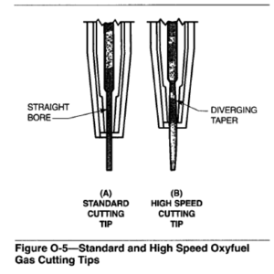
Manual Cutting Tips. Cutting tips are precision-machined copper-alloy parts of various designs and sizes. They are held in the cutting torch by a tip nut. All oxygen cutting tips have preheat flame ports, usually arranged in a circle around a central cutting oxygen orifice. The preheat flame ports and the cutting oxygen orifice are sized for the thickness range of metal that the tip is designed to cut. Cutting tips are designated as standard or high speed. Standard tips have a straight bore oxygen port, and they are usually used with oxygen pressures from 205 to 415 kPa (30 to 60 psi). High-speed tips differ from standard tips in that the exit end of the oxygen orifice flares out or diverges. The divergence allows the use of higher oxygen pressures, typically 415 to 690 Wa (60 to 100psi), while maintaining a uniform oxygen jet at supersonic velocities. High-speed tips are ordinarily used for machine cutting only. They usually permit cutting at speeds approximately 20% greater than speeds available with standard tips. Both types of tips are shown in Figure 0-5.
Gas Pressure Regulators. The ability to make successful cuts also requires a means of precisely regulating the specified gas pressures and volumes. Regulators are pressure control devices used to reduce high source pressures to required working pressures by manually adjusted pressure valves. They vary in design, performance, and convenience features. They are designed for use with specific types of gases and for definite pressure ranges.
Gas pressure regulators used for OFC are generally similar in design to those used for oxyfuel gas welding (OFW). Regulators for most other fuel gases are similar in design to acetylene regulators. For OFC, regulators with higher capacities and delivery pressure ranges than those used for OFW may be required for multi-torch operations and heavy cutting
.
Hoses and Other Equipment. Hoses and such equipment as tip cleaners, wrenches, and strikers used in OFC are the same as those used for OFW.
Safety. Tinted goggles or other appropriate eye protection devices are available in a number of different shades. All appropriate safety devices, including protective clothing, should be used.
Mechanized Equipment
Mechanized OFC will require additional equipment, depending on the application:
(1) A machine to move one or more torches in the required cutting pattern
(2) Torch mounting and adjusting arrangements on the machine
(3) A cutting table to support the work
(4) Means for loading and unloading the cutting table
(5)Automatic preheat ignition devices for multiple torch machines
Mechanized OFC equipment can vary in complexity from simple hand-guided machines to very sophisticated computer-controlled units. The mechanized equipment is analogous to the manual equipment in principle, but differs in design to accommodate higher fuel pressures, faster cutting speeds, and means for starting the cut. Many machines are designed for special purposes, such as those for making vertical cuts, edge preparation for welding, and pipe cutting and beveling. Many variations of mechanized cutting systems are commercially available.
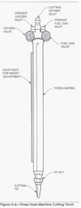
Machine Torches. A typical machine cutting torch consists of a barrel, similar to a manual torch but with heavier construction, and a cutting tip. See Figure 0-6. See also OXYFUEL GAS CUTTING TORCH.
Machine Cutting Tips. Machine cutting tips are designed to operate at higher oxygen and fuel pressures than those normally used for manual cutting. The two-piece divergent bore tip is one type used for operation at high cutting speeds. Divergent bore cutting tips are based on the principles of gas flow through a venturi. High velocities are reached as the gas emerges from the venturi nozzle. Divergent bore cutting tips are precision machined to minimize any distortion of the gases when they exit from the nozzle. They are used for the majority of machine cutting applications because of their superior cutting characteristics for materials up to 150 mm (6 in.) thick. They are not recommended for cutting materials over 250 mm (10 in.) thick.
Cutting Machines. Oxyfuel gas cutting machines are either portable or stationary. Portable machines are usually moved to the work. Stationary machines are fixed in location and the work is moved to the machine.
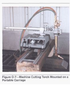
Portable Machines. Portable cutting machines are primarily used for straight-line cutting, although they can be adapted to cut circles and shapes. Portable machines usually consist of a motor driven carriage with an adjustable mounting for the cutting torch. See Figure 0-7. In most cases, the machine travels on a track, which performs the function of guiding the torch. The carriage speed is adjustable over a wide range. The degree of cutting precision depends on both the accuracy of the track, or guide, and the fit between
the track and the driving wheels of the carriage. Portable machines are of various weights and sizes, depending on the type of work to be done. The smallest machines weigh only a few pounds. They are limited to carrying light-duty torches for cutting thin materials. Large, portable cutting machines are heavy and rugged. They can carry one or more heavy-duty torches and the necessary auxiliary equipment for cutting thick sections.
Generally, the operator must follow the carriage to make adjustments, as required, to produce good quality cuts. The operator ignites the torch positions it at the starting point, and initiates the cutting oxygen flow and carriage travel. The operator adjusts torch height to maintain the preheat flames at the correct distance from the work surface. At the completion of the cut, the operator shutsoff the cutting torch and carriage.
Stationary Machines. Stationary machines are designed to remain in a single location.The raw material is moved to the machine, and the cut shapes are transported away. The work station is composed of the machine, a system to supply the oxygen and preheat fuel to the machine, and a material handling system.
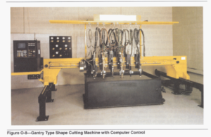
The torch support carriage runs on tracks. The structure either spans the work with a gantry-type bridge across the tracks or it is cantilevered off to one side of the tracks. A gantry machine is shown in Figure 0-8. Cutting machines are usually classified
according to the width of plate that can be cut (transverse motion). The length that can be cut is the travel distance on the tracks. The maximum cutting length is dictated by physical limitations of gas and electric power supply lines. An operator station with consolidated controls for gas flow, torch movement and machine travel is generally a part of the machine.
A number of torches can be mounted on a shape cutting machine, depending on the size of the machine. The machine can cut shapes of nearly any complexity and size. In multiple torch operations, several identical shapes can he cut simultaneously. The number depends on the part size, plate size and the number of available torches.
It is possible to feed information to the electric drive motors of the carriage and cross arm from any suitable control. One method uses a photoelectric cell tracer that can follow line drawings or silhouettes.
Numerical control machines use profile programs placed on punched or magnetic tapes or computer disks. These storage devices, in tum, control the shape cutting by appropriate signals to the cutting machine drive motors.
Operating Procedures
In the operation of OFC equipment, the recommendations of the equipment manufacturer in assembling and using the equipment should always be closely followed. This will prevent damage to the equipment and also insure its proper and safe use.
Procedures
Starting a Cut. Several methods can be used to start a cut on an edge. The most common method is to place the preheat flames halfway over the edge, holding the end of the flame cones 1.5 to 3 mm (1/16 to 1/8 in.) above the surface of the material to be cut. The tip axis should be aligned with the plate edge. When the top comer reaches a reddish yellow color, the cutting oxygen valve is opened and the cutting process starts. Torch movement is started after the cutting action reaches the far side of the edge. Another method is to put the tip entirely over the material to be cut. The preheat flame is held there until the metal reaches its kindling temperature. The tip is then moved to the edge of the plate so the oxygen stream will just clear the metal. With the cutting oxygen on, the cut is initiated. This method has the advantage of producing sharper comers at the beginning of
the cut.
For plate thicknesses of 13 mm (1/2 in.) or more, the cutting tip should be held perpendicular to the plate. For thin plate, the tip can be tilted in the direction of the cut. Tilting increases the cutting speed and helps prevents slag from freezing across the keif.
When cutting material in vertical position, start on the lower edge of the material and cut upward.
Piercing. It is often necessary to start a cut at some point other than on the edge of a piece of metal. This technique is known as piercing. Piercing usually requires a somewhat larger preheat flame than the one used for an edge start. In addition, the flame should be
adjusted to slightly oxidizing to increase the heat energy. The area where the pierce cut is to begin should be located in a scrap area. Hold the torch tip in one spot until the steel surface turns a yellowish red and a few sparks appear from the surface of the metal.
The tip should be angled and lifted up as the cutting oxygen valve is opened. The torch is held stationary until the cutting jet pierces through the plate.
Torch motion is then initiated along the cut line. If the cutting oxygen is turned on too quickly and the torch is not lifted, slag may be blown into the tip and may plug the gas ports.
Machine Cutting. Operating conditions for mechanized oxygen cutting will vary depending on the fuel gas and the style of cutting torch being used. Tip size designations, tip design, and operating data can be obtained from the torch manufacturer.
Proper tip size and cutting oxygen pressure are important in making a quality machine cut. If the proper tip size is not used, maximum cutting speed and the best quality of cut will not be achieved. The cutting oxygen pressure setting is an essential condition; deviations from the recommended setting will greatly affect cut quality. For this reason, some manufacturers specify setting the pressure at the regulator and operating with a given length of hose. When longer or shorter hoses are used, an adjustment in pressure should be made. An alternative is to measure oxygen
pressure at the torch inlet. Pressure settings for cutting oxygen are then adjusted to obtain the recommended pressure at the torch inlet, rather than at the regulator outlet.
Other adjustments, such as the preheat fuel and oxygen pressure settings and the travel speed, are also important. Once the regulators have been adjusted, the torch valves are used to throttle gas flows to give the desired preheat flame. If sufficient flow rates are not obtained, pressure settings at the regulator can be increased to compensate. Cleanliness of the nozzle, type of base metal, purity of cutting oxygen, and other factors have a direct effect on performance.
Manufacturers differ in their recommended travel speeds. Some give a range of speeds for specific thicknesses, while others list a single speed. In either case, the settings are intended only as a guide. In determining the proper speed for an application, begin the cut at a slower speed than that recommended. Gradually increase the speed until cut quality falls below the required level. Then reduce the speed until the cut quality is restored, and continue to operate at that speed.
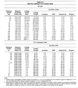
Typical data for cutting low-carbon steel, using commonly available fuel gases, are shown in Table 0-3. The gas flow rates and cutting speeds are to be considered only as guides for determining more precise setting for a particular job. When new material is
being cut, a few trial cuts should be made to ascertain the most efficient operating conditions.
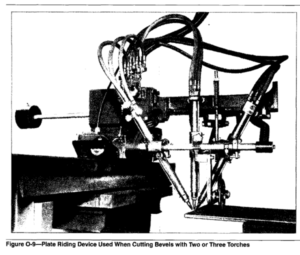
Plate Beveling. The beveling of plate edges before welding is necessary in many applications to insure proper dimensions and fit, and also to accommodate standard welding techniques. Beveling may be done by using a single torch or multiple torches operating simultaneously. Although single beveling can be done manually, beveling is best done by machine for accurate control of the cutting variables. When cutting bevels with two or three torches, plate riding devices should be used to insure constant tip position above the plate, as shown in Figure 0-9.
Cutting Oxidation-Resistant Steels
The absence of alloying materials in pure iron permits the oxidation reaction to proceed rapidly. As the quantity and number of alloying elements in iron increase, the oxidation rate decreases from that of pure iron. Cutting becomes more difficult.
The iron oxides produced have melting points near the melting point of iron. However, the oxides of many of the alloying elements in steels, such as aluminum and chromium, have melting points higher than those of iron oxides. These high-melting oxides, which are refractory in nature, may shield the material in the kerf so that fresh iron is not continuously exposed to the cutting oxygen stream. Thus, the speed of cutting
decreases as the amount of refractory oxide-forming elements in the iron increases.
For ferrous metals with high-alloy content, such as stainless steel, the use of plasma arc cutting (PAC) and in some cases air carbon arc cutting (CAC-A) should
be considered. If these options are not available or practical, then variations of OFC techniques must be used.
There are several variations for oxygen cutting of oxidation resistant steels, which ace also applicable to cast irons. The important ones are the following:
(1)Torch oscillation
(2) Waster plate
(3) Wire feed
(4) Powder cutting
(5)Flux cutting
When the above methods are used to cut oxidation resistant metals, the quality of the cut surface is somewhat impaired. Scale and slag may adhere to the cut faces. Pickup of carbon or iron, or both, usually appears on the cut surfaces of stainless steels and
nickel alloy steels. This may affect the corrosion resistance and magnetic properties of the metal. If the corrosion resistance or magnetic properties of the material are important, approximately 3 mm (1/8 in.) of metal should be machined from the cut edges. See
FLUX CUTTING and METAL POWDER CUTTING.
Torch Oscillation. Low-alloy content stainless steels up to 100 mm (4 in.) thick can sometimes be severed with a standard cutting torch and oscillation. The entire thickness of the starting edge must be preheated to a bright red color before the cut is started. This technique should be combined with some of the other cutting methods listed.
Waster Plate. One method of cutting oxidation resistant steels is to clamp a low-carbon steel “waster” plate on the upper surface of the material to be cut. The cut is started in the low-carbon steel material. The heat liberated by the oxidation of the low-carbon steel provides additional heat at the cutting face to sustain the oxidation reaction. The iron oxide from the low-carbon steel helps to wash away the refractory oxides from stainless steel. The thickness of the waster plate must be in proportion to the thickness of the material being cut. Several undesirable features of this method are the cost of the waster plate material, the additional setup time, the slow cutting speeds, and the rough quality of the cut.
Wire Feed. With the appropriate equipment, a small diameter low-carbon steel wire is fed continuously into the torch preheat flames, ahead of the cut. The end of the wire should melt rapidly into the surface of the alloy steel plate. The effect of the wire addition on the
cutting action is the same as that of the waster plate. A motor-driven wire feeder and wire guide, mounted on the cutting torch, are needed as accessory equipment. This is a seldom-used method.
Safe practices for the installation and operation of oxyfuel gas systems for welding and cutting are given in American National Standard 249.1, latest edition,
published by the American Welding Society, Miami, Florida. These practices and those recommended by the equipment manufacturer should always be followed by the person operating the equipment.
Fumes are a potential health hazard. When the process is used in an enclosed or semi-enclosed area, exhaust ventilation should be provided and the operator should be equipped with a respirator. Noise from the operation may exceed safe levels in some circumstances. When necessary, ear protection should be provided for the operator. Fire is a potential hazard and combustible materials should be cleared away from the cutting area for a distance of at least 11m (35 ft).
Appropriate protective clothing and equipment for any cutting operation will vary with the nature and location of the work to be performed. Some or all of the following may be required:
(1) Tinted goggles or face shields with filter lenses; the recommended filter lenses for various cutting operations are:
(a) Light cutting, up to 25 mm (1 in.) shade 3 or 4
(b) Medium cutting, 25 to 150 mm (1 to 6 in.) shade 4 or 5
(c) Heavy cutting, over 150 mm (6 in.) shade 5 or 6
(2) Flame-resistant gloves
(3)Safety glasses
(4) Flame-resistant jackets, coats, hoods, aprons, etc.
(a) Woolen clothing, preferably, not cotton or synthetic materials
(b) Sleeves, collars, and pockets kept buttoned
(c) Cuffs eliminated
(5)Hard hats
(6)Leggings and spats
(7) Safety shoes
(8) Flame extinguishing protective equipment
(9) Supplemental breathing equipment
(10) Other safety equipment