The arc plasma forms as a result of the electrical heating of any gas to a very high temperature so that its atoms are ionized and conduct electricity.
The plasma arc torch consists of an electrode surrounded by a constricting nozzle which forms a plenum chamber around the electrode. The plasma gas flows through this chamber and is heated and ionized by an electric current between the electrode and the
nozzle or the work. The heating causes the gas to expand greatly and exit a small orifice at the end of the nozzle at big velocity. A pilot arc or high-frequency spark is required to start the main arc.
The plasma gas exits from the nozzle at very high speeds and temperatures; up to 16 000°C (30 000°F) and 6000 m/s (20 000 ft/s). The energy of the arc is concentrated in a small area and thereby produces very rapid beating of the workpiece it impinges.
There are two forms of plasma arc torch operation: transferred arc and non-transferred arc. In the transferred arc mode, the arc current flows between the electrode and the work. This mode of operation is used for welding and cutting. In the non-transferred arc version, the current flows from the electrode to the torch nozzle. The arc within the nozzle heats the plasma gas which exits the nozzle at high speed. This mode of
operation is used for plasma spraying powder, where no electrical connection is made with the work. The extreme heat of the arc is absorbed partly by the water-cooled nozzle and partly by the plasma gas on ionization. When the ionized gas strikes the workpiece, it
gives up its energy to supply heat to the workpiece as it returns to the normal gaseous state.
An arc cutting process that uses a constricted arc and removes the molten metal with a high velocity jet of ionized gas issuing from the constricting orifice.
Plasma arc cutting produces fast, high-quality cuts that often require no further finishing. It accomplishes this by passing an electric current through a column of gas, causing it to ionize and become a plasma. The resulting plasma produces temperatures up
to 16000°C (30000°F). This causes the gas to expand and results in high-velocity flow through the torch orifice. When this high-temperature plasma arc stream strikes a workpiece, it melts the metal rapidly, and the high-velocity jet blows it away. The process makes clean cuts and forms little or no dross or slag on most metals, requires no preheat, and produces a minimum heat-affected zone, with little or no distortion.
While oxyfuel gas cutting is limited to metals which combine with oxygen at elevated temperatures, plasma arc cutting is not limited to this chemical reaction: it is only limited to materials which are electrical conductors.
Historical Background
PAC was invented in the mid 1950s and became commercially successful shortly after its introduction to industry. The ability of the process to sever any electrically conductive material made it especially attractive for cutting nonferrous metals that could not be cut by the oxyfuel cutting (OFC) process. It was initially used for cutting stainless steel and aluminum. As the cutting process was developed, it was found that it had advantages over other cutting processes for cutting carbon steel as well as nonferrous metals.
Advantages and Limitations
Advantages. When compared to mechanical cutting processes, the amount of force required to hold the workpiece in place and move the torch (or vice versa) is much lower with the “non-contact” plasma arc cutting process. Compared to OFC, the plasma cutting
process operates at a much higher energy level, resulting in faster cutting speed. In addition to its higher speed, PAC has the advantage of instant start-up without requiring preheat. Instantaneous starting is particularly advantageous for applications involving
interrupted cutting, such as severing mesh.
Limitations. There are notable limitations to PAC. When compared to most mechanical cutting means, PAC in,troduces hazards such as fire, electric shock, intense light, fumes and gases, and noise levels that may not be present with mechanical processes. It is also difficult to control PAC as precisely as some mechanical processes for close tolerance work. When compared to OFC, the PAC equipment tends to be more expensive, requires a fairly large amount of electric power, and introduces electrical shock hazards.
Principles of Operation
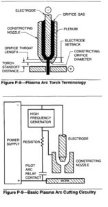
The arc is constricted by passing it through an orifice downstream of the electrode. The basic terminology and the arrangement of the parts of a plasma
cutting torch are shown in Figure P-8. As plasma gas passes through the arc, it is heated rapidly to a high temperature, expands, and is accelerated as it passes through the constricting orifice toward the workpiece. The intensity and velocity of the plasma is determined by several variables including the type of gas, its pressure, the flow pattern, the electric current, the size and shape of the orifice, and the distance to the workpiece. Plasma arc cutting circuitry is shown in Figure P-9. The process operates on direct current, straight polarity. The orifice directs the super-heated plasma stream from the electrode toward the workpiece. When the arc melts the workpiece, the high velocity jet blows away the molten metal to form the kerf, or cut. The cutting arc attaches to or “transfers” to the workpiece, and is referred to as a transferred arc.
The gases used for plasma arc cutting include nitrogen, argon, air, oxygen, and mixtures of nitrogen/ hydrogen and argon-hydrogen.
The most common pilot arc starting technique is to strike a high-frequency spark between the electrode and the torch tip. A pilot arc is established across the resulting ionized path. When the torch is close enough to the workpiece so the plume or flame of the pilot arc touches the workpiece, an electrically conductive path from the electrode to the workpiece is established. The cutting arc will follow this path to the workpiece.
Equipment
Torches. The plasma cutting process is used with either a hand-held torch or a mechanically-mounted torch. There are several types and sizes of each, depending on the thickness of metal to be cut. Some torches can be dragged along in direct contact with the
workpiece, while others require that a standoff be maintained between the tip of the torch and workpiece.
Certain plasma arc torch parts must be considered to be consumable. The tip and electrode are the most vulnerable to wear during cutting, and cutting performance deteriorates as they wear. The timely replacement of consumable parts is required to achieve good quality cuts.
Power Supplies. Plasma arc cutting requires a constant current or drooping volt-ampere characteristic, relatively high-voltage, direct-current power supply. To achieve satisfactory arc starting performance, the open circuit voltage of the power supply is generally about twice the operating voltage of the torch. Operating voltages will range from 50 or 60 volts to over 200 volts so PAC power supplies will have open circuit voltages ranging from about 150to over 400 volts.
Newer types of plasma cutting power supplies include electronic phase control and various types of “switch mode,” or inverter, power supplies. The switch mode power supplies utilize high-speed, high-current semiconductors to control the output. They can
either regulate the output of a standard DC power supply, the so-called “chopper” power supply, or they can be incorporated in an inverter-type power supply.
As new types of semiconductors become commercially available, it can be expected that improved versions of this type of power supply will appear. Switch mode supplies have the advantage of higher efficiency and smaller size, and are attractive for
applications where portability and efficiency are important considerations.
Motion Equipment. A variety of motion equipment is available for use with mechanized plasma cutting torches. This equipment can range from straight-line tractors to numerically-controlled or direct computer-controlled cutting machines with parts nesting capabilities, etc. Plasma cutting equipment can also be adapted to robotic actuators for cutting other than flat plates.
Environmental Controls. The plasma cutting process is inherently a noisy and fume-generating process. Several different devices and techniques are available to control and contain the hazards. One commonly used approach to reduce noise and fume emissions is
to cut over a water table and surround the arc with a water shroud. This method requires a cutting table filled with water up to the work-supporting surface, a water shroud attachment for the torch, and a recirculating pump to draw water from the cutting table and pump it through the shroud. In this case, a relatively high 55 to 75 W/min (15 to 20 gpm) water flow is used.
Another method, underwater plasma cutting, is also in common use. With this method, the working end of the torch and the plate to be cut are submerged under approximately 75 mm (3 in.) of water. While the torch is underwater but not cutting, a constant flow of compressed air is maintained through the torch to keep water out.
The primary requirements in water table design are adequate strength for supporting the work, sufficient scrap capacity to hold the dross or slag resulting from cutting, procedure for removing the slag, and ability to maintain the water level in contact with the work.
When the table is used for underwater cutting, it is necessary to provide a means of rapidly raising and lowering the water level. This can be accomplished by pumping the water in and out of a holding tank, or by displacing it with air in an enclosure under the surface of the water.
A cutting table for mechanized or hand plasma cutting is usually equipped with a down-draft exhaust system. This is vented to the outdoors in some cases, although fume removal or filtering devices may be required to meet air pollution regulations.
Applications
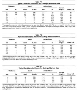
The first commercial application of plasma arc cutting was the mechanized cutting of manway holes on aluminum railroad tank cars at the Graver Tank plant in Edgemoor, Delaware. In five minutes the plasma arc torch produced a beveled, ready-to-weld joint, in a 16 mm (51’8 in.) thick shell that previously took five hours to prepare. The process has since been used on a wide variety of aluminum applications. Table P-1
shows typical conditions for mechanized cutting of aluminum plate.
Typical conditions for mechanized cutting of stainless steel plate are shown in Table P-2.
Manual plasma arc cutting is widely used in automobile body repair for cutting high-strength low-alloy (HSLA) steel. Instant starting and high travel speeds reduce heat input to the high-strength, low-alloy steel and help maintain its strength.
The chief application of mechanized plasma arc cutting of carbon steel is for thicknesses up to 13 mm (1/2 in.). The higher cost of plasma arc equipment compared to oxyfuel cutting (OFC) equipment can be justified by the former’s higher cutting speeds. Conditions for mechanized plasma arc cutting of carbon steel plate are shown in Table P-3.
The plasma process has been used for stack cutting of carbon steel, stainless steel, and aluminum. The plates to be stack-cut should preferably be clamped together, but PAC can tolerate wider gaps between plates than OFC.
Plate and pipe edge beveling is done by using techniques similar to those for OFC. One to three PAC torches are used, depending on the joint preparation required.
Cut Quality
Factors to consider in evaluating the quality of a cut include surface smoothness, kerf width, kerf angle, dross adherence, and squareness of the top edge. These factors are affected by the type of material being cut, the equipment being used, and the cutting
conditions.
Plasma cuts in plates up to approximately 75 mm (3 in.) thick may have a surface smoothness very similar to that produced by oxyfuel gas cutting.
Kerf widths of plasma arc cuts are 1-1/2 to 2 times the width of oxyfuel gas cuts in plates up to 50 mm (2 in.) thick. For example, a typical kerf width in 25 mm (1 in.) stainless steel is approximately 5 mm (3/16 in.). Kerf width increases with plate thickness. A plasma cut in 180 mm (7 in.) stainless steel made at approximately 3 mm/s (4 in./min) has a kerf width of 28 mm (1-1/8 in.).
The plasma jet tends to remove more metal from the upper part of the kerf than from the lower part. This results in beveled cuts wider at the top than at the bottom. A typical included angle of a cut in 25 mm (1 in.) steel is four to six degrees. This bevel
occurs on one side of the cut when orifice gas swirl is used. The bevel angle on both sides of the cut tends to increase with cutting speed.
Dross is the material that melts during cutting and adheres to the bottom edge of the cut face. With mechanized equipment, dross-free cuts can be produced on aluminum and stainless steel up to approximately 75 mm (3 in.) thickness and on carbon steel up to
approximately 40 mm (1-1/2 in.) thickness. With carbon steel, selection of speed and current are more critical. Dross is usually present on cuts in thick materials.
Top edge rounding will result when excessive power is used to cut a given plate thickness or when the torch standoff distance is too large. It may also occur in high-speed cutting of materials less than 6 mm (1/4 in.) thick. Examples of high-definition (square edge, dross-free) plasma arc cuts in carbon and stainless steel are shown in Figure P-10.
Metallurgical Effects
During PAC, the material at the cut surface is heated to its melting temperature and ejected by the force of the plasma jet. This produces a heat-affected zone along the cut surface, as with fusion welding operations. The heat not only alters the structure of the metal in this zone, but also introduces internal tensile stresses from the rapid expansion, upsetting, and contraction of the metal at the cut surface.
The depth to which the arc heat will penetrate the workpiece is inversely proportional to cutting speed. The heat-affected zone on the cut face of a 25 mm
(1 in.) thick stainless steel plate severed at 21 mds (50 in./min) is 0.08 to 0.13 mm (0.003 to 0.005 in.) deep. This measurement was determined from microscopic examination of the grain structure at the cut edge of a plate.
Because of the high cutting speed on stainless steel and the quenching effect of the base plate, the cut face passes through the critical 650°C (1200’F) temperature very rapidly. Thus, there is virtually no chance for chromium carbide to precipitate along the grain boundaries, so corrosion resistance is maintained. Measurements of the magnetic properties of Type 304 stainless steel made on base metal and on plasma arc cut samples indicate that magnetic permeability is unaffected by arc cutting.
Metallographic examination of cuts in aluminum plates indicates that the heat-affected zones in aluminum are deeper than those in stainless steel plate of the same thickness. This results from the higher thermal conductivity of aluminum. Microhardness surveys indicate that the heat effect penetrates about 5 mm (3/16 in.) into a 25 mm (1 in.) thick plate. Age-hardenable aluminum alloys of the 2000 and 7000 series are crack-sensitive at the cut surface. Cracking appears to result when a grain boundary eutectic film melts and separates under stress. Machining to remove the cracks may be necessary on edges that will not be welded.
Hardening will occur in the heat-affected zone of a plasma arc cut in high-carbon steel if the cooling rate is very high. The degree of hardening can be reduced by preheating the workpiece to reduce the cooling rate at the cut face.
Various metallurgical effects may occur when long, narrow, or tapered parts, or outside comers are cut. The heat generated during a preceding cut may reach and adversely affect the quality of a following cut
Safety
The potential hazards of plasma arc cutting and gouging are similar to those of most arc welding and cutting. The following information concerns the less obvious hazard categories of electrical shock, fume and gas generation, noise, and radiation.
Emergency first aid should he available. Prompt, trained emergency response may reduce the extent of injury due to accidental electrical shock. Only trained personnel should be permitted to operate or maintain the equipment. In addition to the manufacturer’s instructions, the following may be of assistance:
(1) ANSI C-2, the National Electrical Safety Code
(2) ANSI 249.1, Safety in Welding and Cutting
(3) 29CFR1910, OSHA General Industry Standards
(4) NFPA Standard 51B, Fire Prevention in the Use of Cutting and Welding Processes.
The equipment should not be operated until the manufacturer’s instructions have been read and understood. In addition, other potential physical hazards such as those due to the high-pressure gas and water systems must be considered.
Some cutting gas mixtures contain hydrogen. Inadvertent release of such gases can result in explosion and fire hazards. The equipment should not be operated when gas leaks are suspected. The manufacturer should be contacted if there is a question about the
equipment operation with certain gases.
Electrical. Voltages used in plasma cutting equipment range from 150 to 400 V direct current. Electric shock can be fatal. The equipment must be properly grounded and connected as recommended by the manufacturer.
Some additional safety items are listed below:
(1) Keep all electrical circuits dry. Moisture may provide an unexpected path for current flow. Equipment cabinets that contain water and gas lines as well as electrical circuits should be checked periodically for leaks. All electrical connections should be kept mechanically tight. Poor electrical connections can generate heat and start fires.
(2) All electrical connections should be kept mechanically tight. Poor electrical connections can generate heat and start fires.
(3) Cable insulated for high voltage should be used. Make sure cables and wires are kept in good repair. Consult the manufacturer’s instructions for proper cable and wire sizes.
(4) Do not touch live circuits. Keep equipment access doors closed.
(5) The risk of electrical shock is probably the greatest when replacing used torch parts. Operators must make sure that the primary power to the power supplies and the power to the control circuitry is disconnected when replacing torch parts.
(6) Operators and maintenance personnel should be aware that plasma arc cutting equipment, due to the higher voltages, presents a greater hazard than conventional welding equipment.
Fumes and Gases. Plasma arc cutting produces fumes and gases which can harm the operator’s health. The composition and rate of generation of fumes and gases depend on many factors including arc current, cutting speed, material being cut, and gases used. The fume and gas by-products will usually consist of the oxides of the metal being cut, ozone, and oxides of nitrogen.
These fumes must be removed from the work area or eliminated at the source by using an exhaust system. Codes may require that the exhaust be filtered before being vented to the atmosphere.
There is a possibility of hydrogen detonation beneath the workpiece when cutting aluminum or magnesium plate on a water table. This can be caused by hydrogen released by the interaction of molten aluminum or magnesium and water. The hydrogen can accumulate in pockets under the workpiece and ignite when the cutting arc is near the pocket. Before cutting aluminum or magnesium on a water table, the equipment manufacturer should be contacted for recommended practices.
Noise. The amount of noise generated by a PAC torch operated in the open depends primarily on the cutting current. A torch operating at 400 A typically generates approximately 100 dB A measured at about six feet. At 750 A the noise level is about 110 dBA. Much of the noise is in the frequency range of 5000 to 20000 Hz. Such noise levels can damage hearing. Hearing protection should be worn when the noise level exceeds specified limits. These values may vary locally and are specified by OSHA for most industrial environments.
The water-shroud technique is commonly used to reduce noise in mechanized cutting applications. The water effectively acts as a sound-absorbing enclosure
around the torch nozzle. The water directly below the plate keeps noise from coming through the kerf opening.
Radiation. The plasma arc emits intense visible and invisible (ultraviolet and infrared) radiation. In addition to potential harm to the eyes and skin, this radiation may produce ozone, oxides of nitrogen, or other toxic fumes in the surrounding atmosphere.
It is necessary to wear eye and skin protection when exposure to radiation is unavoidable. The recommended eye protection is shown in 18. The likelihood of radiation exposure may be reduced by the use of mechanical barriers such as walls and welding curtains. The water shroud will also act as a light-absorbing shield, especially when dye is added to the water in the table. When the use of dye is contemplated, contact the equipment manufacturer for information on the type and concentration to use. It is
advisable to provide operator eye protection, even when using these dyes, because of the possibility of unexpected interruption of water flow through the water shroud. See PLASMA ARC and PLASMA ARC WELDING.
A device used to transfer current to a fixed cutting electrode, position the electrode, and direct the flow of shielding gas and orifice gas.