Steels clad with a nickel alloy are frequently joined by welding. Since the cladding is normally used for its corrosion resistance, the cladding alloy must be continuous over the entire surface of the structure, including the welded joints. This requirement influences joint design and welding procedure. Butt joints should be used when possible.
Figure N-4 shows recommended weld joint designs for two thickness ranges [see (A) and (B)]. Both designs include a small root face of unbeveled steel above the cladding to protect the cladding during welding of the steel. The steel side should be welded first with a low-hydrogen filler metal. It is important to avoid fusion of the cladding during the first welding pass.
Dilution of the steel weld with the nickel-alloy cladding can cause cracking of the weld metal. The clad side of the joint should be prepared by grinding or chipping and welded with the filler metal recommended for cladding. The weld metal will be diluted
with steel. To maintain corrosion resistance, at least two layers, and preferably three or more, should be applied.
The strip-back method is sometimes used instead of the procedure described above. The cladding is removed from the vicinity of the joint as shown in Figure N-4 (C). The steel is then welded using a standard joint design and technique for steel, and the nickel-alloy cladding is reapplied by weld cladding. The advantage of the strip-back method is that it eliminates the possibility of cracking caused by penetration of the steel weld metal into the cladding.
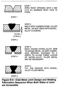
Some joints, such as those in closed vessels or tubular products, are accessible only from the steel side. In such cases, a standard joint design for steel is used, and the cladding at the bottom of the joint is welded first with nickel alloy weld metal. After the cladding is welded, the joint can be completed with the appropriate nickel alloy weld metal, or a barrier layer of carbon-free iron can be applied and the joint completed
with steel weld metal. If the thickness of the steel is 8 mm (5/16 in.) or less, it is usually more economical to complete the joint with nickel alloy welding filler metal. Figure N-5 shows the most commonly used fabrication sequence when both sides are accessible.
cutting, so that the molten metal is blown out of the cut as the torch progresses.
Gases used for plasma cutting include argon-hydrogen mixtures, nitrogen-hydrogen mixtures, oxygen and nitrogen. The choice of gas depends on the application and the type of equipment used. The equipment manufacturer’s recommendations should
be followed.
Cuts up to 150 mm (6 in.) thick have been made in high-nickel alloys. Because of the constricted plasma jet and the speed of the process, heat-affected zones are usually only 0.25 to 0.4 mm (0.010 to 0.015 in.) wide. The cut surfaces of sections thinner than 75 mm (3 in.) are superior to those produced by the powder cutting process. They are similar to sheared edges but have less bevel. For many applications they can be
welded without intermediate cleaning operations. Quality of cuts in heavy sections is about equal to that of cuts produced by powder cutting.
Air Carbon Arc Cutting (CAC-A). This process is more effective for gouging operations than for cutting and is widely used for back-gouging on welds and for the removal of fillet welds. By controlling the depth of the groove, limited thicknesses of material can be cut. Grooves up to 25 mm (1 in.) deep can be made in a single pass, but increments of 1 mm (0.004 in.) can also be removed. The width of the groove is determined primarily by the size of electrode. Torch angle and speed affect depth of the groove and the heat-affected zone.
Laser Beam Cutting (LBC). Laser beam cutting is a thermal cutting process that severs material by locally melting or vaporizing, with the heat generated by a laser beam. The process is used with or without assist gas to aid in the removal of molten and vaporized
material.
Laser cutting has the advantage of high speeds, narrow kerf widths, high quality edges, low heat input, and minimum workpiece distortion. It is an easily automated process that can cut most metals.
Most nickel-base alloys are intended for some form of severe service, i.e., high temperatures or corrosive environments. While these metals are easily laser-cut, it is usually necessary to examine the workpiece for such metallurgical defects as microcracking and grain growth to ensure that the part will perform properly.
Water Jet Cutting. Water jet cutting severs metals and other hard materials using a high-velocity water jet. The water stream, with a flow rate of 0.4 to 19 L/min (0.8 to 40 ft3/h is usually manipulated by a robot or gantry system, but small workpieces maybe guided past a stationary water jet by hand. Metals and other hard materials are cut by adding an abrasive in powder form to the water stream. Higher flow rates of water are required to accelerate the abrasive particles.
Materials are cut cleanly, without ragged edges, without heat, and generally faster than on a band saw. A smooth, narrow 0.8 to 2.5 mm (0.030 to 0.100 in.) kerf is produced. There is no problem of thermal delamination, or deformation, when water jet cutting is properly applied.
Metal Powder Cutting (POC). Metal powder cutting is based on the use of an oxygen jet into which finely divided powder is fed. The powder initiates an exothermic reaction that supplies the heat necessary for cutting. Nickel alloys can be readily cut with an iron powder or mixtures of iron and aluminum powders.
In powder cutting, considerable amounts of oxide and burned material accumulate on the metal, with the greatest buildup occurring on the top surface. This slag is more adherent on nickel-copper alloys than on nickel or nickel-chromium alloys. All adherent slag, powder or dross must be removed prior to any further operation.
The depth affected by heat from powder cutting is extremely shallow. Corrosion resistance of the metal is not impaired if all discoloration is removed.