An arc welding process that uses an arc or arcs between a bare metal electrode or electrodes and the weld pool. The arc and molten metal are shielded by a blanket of granular flux on the workpieces. The process is used without pressure and with electrode filler metal and sometimes of a supplemental material (welding rod, flux, or metal granules). See also HOT WIRE WELDING and SERIES SUBMERGED ARC WELDING.
In submerged arc welding, the arc is covered by a flux. This flux plays a main role in that (1) the stability of the arc is dependent on the flux, (2) mechanical and chemical properties of the final weld deposit can be controlled by flux, and (3) the quality of the weld may be affected by the care and handling of the flux.
Submerged arc welding is a versatile production welding process capable of making welds with currents up to 2000 amperes, ac or dc, using single or multiple wires or strips of filler metal. Both a-c and d-c power types may be used on the same weld at the same time.
Principles of Operation
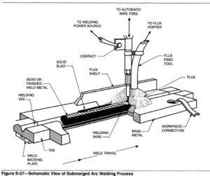
In submerged arc welding, the end of a continuous bare wire electrode is inserted into a mound of flux that covers the area or joint to be welded. An arc is initiated using one of six arc-starting methods (See ARC STARTING METHODS). A wire-feeding mechanism then begins to feed the electrode wire toward the joint at a controlled rate, and the feeder is moved manually or automatically along the weld seam. For machine or automatic welding, the work may be moved beneath a stationary wire feeder.
Additional flux is continually fed in front of and around the electrode, and continuously distributed over the joint. Heat evolved by the electric arc progressively melts some of the flux, the end of the wire, and the adjacent edges of the base metal, creating a pool of molten metal beneath a layer of liquid slag. The melted bath near the arc is in a highly turbulent state. Gas bubbles are quickly swept to the surface of the pool. The flux floats on the molten metal and completely shields the welding zone. The liquid flux may conduct some electric current between the wire and base metal, but an electric arc is the predominant heat origin. The flux blanket on the top surface of the weld pool prevents atmospheric gas contaminatation, and dissolves impurities in the base metal and electrode and floats them to the surface. The flux can also add or remove certain alloying elements to the weld metal.
As the welding zone progresses along the seam, the weld metal and then the liquid flux cool and solidify, forming a weld bead and a protective slag shield over it.
It is important that the slag is completely removed before making another weld pass. The submerged arc process is illustrated in Figure S-27.
(1) The chemical composition and mechanical properties required of the final deposit
(2) Thickness of base metal to be welded
(3) Joint accessibility
(4) Position in which the weld is to be made
(5) Frequency or volume of welding to be performed.

Submerged arc welding can be applied in three different modes: semiautomatic, automatic, and machine. Each method requires that the work be positioned so that the flux and the molten weld pool will remain in place until they have solidified. Many types of fixtures and positioning equipment are available or can be built to satisfy this requirement.
Semiautomatic Welding- Semiautomatic welding is done with a hand-held welding gun, which delivers both flux and the electrode. The electrode is driven by a wire feeder. Flux may be supplied by a gravity bopper mounted on the gun or pressure fed through a hose.
This method features manual guidance using relatively small diameter electrodes and moderate travel speeds. The travel may be manual or driven by a small gun mounted driving motor.
Automatic Welding- Automatic welding is done with equipment that performs the welding operation without requiring a welding operator to continually monitor and adjust the controls. The expense of self-regulating equipment can be justified in order to achieve high production rates.
Machine Welding- Machine welding employs equipment that performs the complete welding operation. However, it must be monitored by a welding operator to position the work, start and stop welding, adjust the controls, and set the speed of each weld.
The principles which favor the use of ac to minimize arc blow in single arc welding are often applied in multiple arc welding to create a favorable arc deflection. The current flowing in adjacent electrodes sets up interacting magnetic fields that can either reinforce or diminish each other. In the space between the arcs, these magnetic fields are used to produce forces that will deflect the arcs (and thus distribute the heat) in directions beneficial to the intended welding application.
Equipment
The equipment required for submerged arc welding consists of (1) a power supply, (2) an electrode delivery system, (3) a flux distribution system, (4) a travel arrangement, and (5) a process control system. Optional equipment includes flux recovery systems and positioning or manipulating equipment.
Process Variations
Submerged arc welding lends itself to a wide variety of wire and flux combinations, single and multiple electrode arrangements, and use of a-c or d-c welding power supplies. The process has been adapted to a wide range of materials and thicknesses. Various multiple arc configurations may be used to control the weld profile and increase the deposition rates over single arc operation. Weld deposits may be found in the range of
Fluxes for stainless steel SAW are proprietary. Manufacturers of fluxes should be consulted for recommendations. Submerged arc fluxes are available in fused and bonded types for welding stainless alloys. Some bonded fluxes contain chromium, nickel, molybdenum, or niobium to replace elements lost across the arc. The newer chemically basic fluxes have shown more consistent element recovery than earlier, less basic or acid types. Performance of fluxes for stainless steel weldments may depend on the user’s care in flux handling and reuse. Over-recycled fluxes will become depleted in compensating elements. Refer to the manufacturer’s recommendation for handling and recycling of flux.
Combination Power Supplies- Power supplies that can be switched between CV and CC modes are also available. Supplies rated at up to 1500 A are available, but machines rated at 650 A or less are much more common. The value of these power supplies lies in their versatility, since they can be used for SMAW, GMAW, GTAW, FCAW, air carbon arc cutting, and stud welding, in addition to submerged arc welding.
Alternating-Current Power Supplies- Alternating current welding power supplies rated for 800 to 1500 A at 100% duty cycle are available. If higher amperages are required, these machines can be connected in parallel.
Conventional a-c power supplies are the constant current type. The output of these machines drops to zero with each polarity reversal, so a high open circuit voltage (greater than 80 V) is required to ensure reignition of the arc. Even at that high open circuit voltage, arc re-ignition problems are sometimes encountered with certain fluxes. Because these power supplies are the constant-current type, the speed controls must be voltage sensing, variable wire feed type.
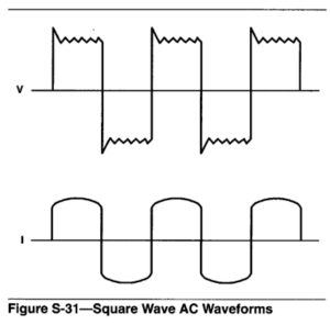
The constant-voltage square wave a-c power supply is a relatively new type. Both the output current and the output voltage of these these supplies approximate square waves. Because polarity reversals are instantaneous with square wave supplies, as is shown in Figure S-31, arc re-ignition problems are not as severe as those encountered with conventional a-c supplies. Hence, some fluxes that do not work with conventional a-c supplies will work with square wave a-c supplies. Relatively simple constant wire feed speed controls can be used with square wave supplies, since they supply constant voltage.

The most common uses of a-c power for SAW are high-current applications, multiwire applications, narrow-gap welding, and applications where arc blow is a problem.
Controls
The state-of-the-art wire feeders used for automatic SAW have microprocessor-based digital controls. These controls have feedback loops interfaced with the power supply and wire feed motor, to maintain the welding voltage and wire speed at preset values. The great advantage of digital controls is their precise control of the welding process. The disadvantages are that the controls are not compatible with some power supplies, and they are not as rugged as most analog controls.
Weld Heads and Torches
A submerged arc welding head comprises the wire feed motor and feed roll assembly, the torch assembly and contact tip, and accessories for mounting and positioning the head. A flux nozzle is usually mounted on the weld head, to deposit the flux either slightly ahead of or concentric with the welding wire.
Wire feed motors are typically heavy duty, permanent magnet-type motors with an integral reducing gearbox, feeding wire at speeds in the range of 8 to 235 mrn/sec (20 to 550 in./min.).
The feed roll assembly may have one drive and one idler roll, two drive rolls, or four drive rolls. Four-roll drive assemblies are reported to provide positive feeding with the least wire slippage. Feed rolls may be knurled-V or smooth-V type; knurled-V rolls are the most common. In some cases, where the wire is being pushed through a conduit, smoother feeding will result if smooth V-groove rolls are used.
The torch assembly guides the wire through the contact tip to the weld zone, and also delivers welding power to the wire at the contact tip.
Special equipment is needed for narrow groove (SAW-NG) and strip electrode SAW. Parallel wire SAW uses special feed roll and torch assemblies that provide positive feeding of two wires through one torch body. Strip electrode SAW also requires a special feed roll and torch assembly. Torches that feed strip are generally adjustable to accommodate several sizes of strip, typically 30, 45, 60, 90 mm (1.2, 1.8, 2.4, 3.5 in.) wide, and up to 1 mm thick (0.04 in.) thick. The assemblies for parallel wire and strip electrode SAW are generally designed for mounting on standard welding heads with little or no modification. The special SAW-NG equipment has long narrow torch assemblies and long narrow flux nozzles to deliver the flux and wire to the bottom of deep narrow grooves. These systems may also have some means to bend the wire to assure good side wall fusion in the narrow groove. Simple SAW-NG adaptors can be mounted directly on standard weld heads; more complex systems are available as complete weld head assemblies.
For semiautomatic SAW, the weld head may be a GMAW-type wire feeder that pushes the electrode through a conduit to the torch assembly. Such wire feeders accept any of the drive roll systems previously described, and are generally capable of feeding wire up to 2.4 mm (3/32 in.) in diameter at wire feed speeds over 235 mm/s (550 in./min). The torch-conduit assembly allows for welding up to 4.6 m (15 ft) out of the wire feeder. Flux feed is provided either by a small 1.8 kg (4lb) gravity feed flux hopper mounted on the torch, or a remote flux tank that uses compressed air to convey the flux to the weld zone. In both cases, the flux is delivered through the torch surrounding the welding wire.
Accessory Equipment
Accessory equipment commonly used with SAW includes travel equipment, flux recovery units, fixturing equipment, and positioning equipment.
Travel Equipment- Weld head travel in SAW is generally provided by a tractor-type carriage, a side beam carriage, or a manipulator.
A tractor-type carriage provides travel along straight or gently curved weld joints by riding on tracks set up along the joint, or by riding on the workpiece itself. Trackless units use guide wheels or some other type of mechanical joint-tracking device. The weld head, control, wire supply, and flux hopper are generally mounted on the tractor. Maximum travel speeds possible with tractors are about 45 mm/s (100 in./min). Tractors find the most use in field welding where their relative portability is necessary because the workpiece cannot be moved. Side beam carriages provide linear travel only, and are capable of travel speeds in excess of 85 mm/s (200 in./min). Because side beam systems are generally fixed and the workpiece must be brought to the weld station, their greatest use is for shop welding.
The weld head, wire, flux hopper, and sometimes the control are mounted on the carriage.
Manipulators are similar to side beams, in that they are fixed and the workpiece must be brought to the welder. Manipulators are more versatile than side beams in that they are capable of linear motion in three axes. The weld head, wire, flux hopper, and often the control and operator ride on the manipulator.
Flux recovery units are frequently used to maximize flux utilization and minimize manual clean-up.
Flux recovery units may do any combination of the following:
(1) Remove unfused flux and fused slag behind the weld head
(2) Screen out fused slag and other oversized material
(3) Remove magnetic particles
(4) Remove fines
(5) Recirculate flux back to a hopper for reuse
(6) Heat flux in a hopper to keep it dry.
Pneumatic flux feeding is commonly used in semiautomatic SAW and frequently in automatic SAW.
Positioners and Fixtures- Because SAW is limited to flat position welding, positioners and related fixturing equipment find widespread use. Commonly used positioners include:
(1) Head-tailstock units, turning rolls, or both, to rotate cylindrical parts under the weld head
(2) Tilting-rotating positioners, to bring the area to be welded on irregular parts into the flat position Custom fixturing often includes positioners to aid in setting up, positioning, and holding the workpiece. Turnkey systems are available.
Materials
Submerged arc welding is used to fabricate most materials in general use, including “plain” carbon steels to exotic nickel-base alloys. Most steels and alloys are readily weldable with commercially available wires and fluxes.
Electrodes
Submerged arc electrodes produce weld deposits matching carbon steel, low- alloy steel, high-carbon steels, special alloy steels, stainless steels, nickel alloys, and special alloys for surfhcing applications. These electrodes are supplied as bare solid wire and as composite metal-cored electrodes (similar to flux-cored arc welding electrodes).
Electrodes are normally packaged as coils or drums range in weight starting at 11 and going to 454 kg (25 to 1000 lb). Large electrode packages are economical because they increase operating efficiency and eliminate end-of-coil waste.
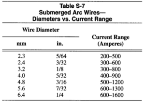
Submerged arc welding electrodes vary in size in the range of 1.6 to 6.4 mm (1/16 to 1/4 in.) in diameter. General guidelines for amperage range selection are presented in Table S-7. The wide amperage ranges are typical of submerged arc welding. Refer to ANSI /AWS A5.17, Specification for Carbon Steel Electrodes and Fluxes for Submerged Arc Welding.

Fluxes are granular mineral compounds mixed according to various formulations. Based on the choice of several manufacturing methods, the different types of fluxes are fused, bonded (also known as agglomerated), and mechanically mixed.
Fused Fluxes- The raw materials of a fused flux are mixed dry and melted in an electric furnace. After melting, the furnace charge is poured and cooled. Cooling may be accomplished by shooting the melt through a stream of water or by pouring it onto large chill blocks. The result is a product with a glassy appearance which is then crushed, screened for size, and packaged.
Fused fluxes have the following advantages:
(1) Good chemical homogeneity
(2) Easy removal of the fines without affecting the flux composition
(3) Normally will not absorb moisture, which simplifies handling, storage, and welding problems
(4) Readily recycled through feeding and recovery systems without significant change in particle size or composition.
Their main disadvantage is the difficulty of adding deoxidizers and ferro-alloys to them during manufacture without segregation or extremely high losses. The high temperatures needed to melt the raw ingredients limit the range of flux compositions.
Bonded Fluxes- To manufacture a bonded flux, the raw materials are powdered, dry mixed, and bonded with either potassium silicate, sodium silicate, or a mixture of the two. After bonding, the wet mix is pelletized and baked at a temperature lower than that used for fused fluxes. The pellets are then broken up, screened to size, and packaged. The advantages of bonded fluxes include the following:
(1) Easy addition of deoxidizers and alloying elements; alloying elements are added as ferro-alloys or as elemental metals to produce alloys not readily available as electrodes, or to adjust weld metal compositions
(2) Usable with thicker layer of flux when welding
(3) Color identification
The disadvantages are the following:
(1) Tendency for some fluxes to absorb moisture in a manner similar to coatings on some shielded metal arc electrodes
(2) Possible gas evolution out of the molten slag
(3) Possible change in flux composition due to segregation or removal of fine mesh particles.
Mechanically Mixed Fluxes- To produce a mechanically mixed flux, two or more fused or bonded fluxes are mixed in any ratio necessary to yield the desired resu1ts.The advantage of mechanically mixed fluxes is that several commercial fluxes may be mixed for highly critical or proprietary welding operations. The following are disadvantages of mechanically mixed fluxes:
(1) Segregation of the combined fluxes during shipment, storage, and handling
(2) Segregation occurring in the feeding and recovery systems during the welding operation
(3) Inconsistency in the combined flux between mixes
Flux Usage- In applications where low hydrogen considerations are important, fluxes must be kept dry. Fused fluxes do not contain chemically bonded H20, but the particles hold surface moisture. Bonded fluxes contain chemically bonded H20,and may hold surface moisture as well. Bonded fluxes need to be protected in the same manner as low-hydrogen shielded metal arc electrodes. The user should follow the directions of the flux manufacturer for specific baking procedures.
Fluxes are identified as chemically basic, chemically acid, or chemically neutral. The basic or acid quality of a flux is related to the ease with which the component oxides of the flux ingredients dissociate into a metallic ion with a positive charge and a negatively charged oxygen ion. Chemically basic fluxes are normally high in MgO or CaO, while chemically acid fluxes are normally high in SO2. The basicity or acidity of a flux is often referred to as the ratio of CaO or MgO to Si02. Fluxes having ratios greater than one are called chemically basic. Ratios near unity are chemically neutral. Those less than unity are chemically acidic.
Welding of Carbon Steel Materials
Carbon steel materials are usually welded with electrode and flux combinations classified under AWS Standard A5.17, Carbon Steel Electrodes and Fluxes for Submerged Arc Welding. Typical steels that are welded with these consumables are listed in ANSV AWS D1.l, Structural Welding Code-Steel, as Group I and I1 classifications. These steels include ASTM A106 Grade B, A36, A516 Grades 55 to 70, A537 Class 1, A570 Grades 30 to 50, API 5LX Grades X42 to X52, and ABS Grades A to EH36. These steels are usually supplied in the as-rolled or the normalized condition.
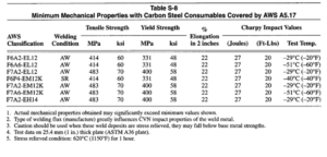
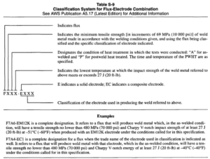
Table S-8 lists minimum mechanical properties for various wire/flux combinations. When selecting SAW consumables, it is required that both the minimum tensile and minimum yield strengths as well as the notch toughness properties (when required) of the weld metal be matched with the base metal. AWS Filler Metal Comparison Charts show the commercial products that meet the AWS wire-flux classifications listed in Table S-8. In special applications, particularly carbon steel weldments subject to long term postweld heat treatment, low-alloy submerged arc welding consumables covered by ANSVAWS A5.23, Specifications for Low Alloy Steel Electrodes and Fluxes, may be required to meet tensile properties of the base metal. Table S-9 shows the classification system for flux-electrode combinations. Fluxes are classified on the basis of weld metal properties obtained when used with specific electrodes.

.png)
ANSVAWS A5.23 lists welding consumables used with carbon steel base materials to meet special notch toughness requirements. Actual mechanical properties obtained may significantly exceed minimum values shown.
Special Service Conditions- Some carbon steel components that are submerged arc welded will be used in special service conditions where the hardness of the weld metal, heat-affected zone, and plate must not exceed a specified maximum level. This is usually required in the oil industry, where the component will be exposed to wet hydrogen sulfide gas. It has been found that if the hardness is kept below a prescribed level, depending on the type of material and the service conditions, stress corrosion cracking will generally not occur.
Stainless Steels
Stainless steels are capable of meeting a wide range of properties, such as corrosion resistance, strength at elevated temperatures, and toughness at cryogenic temperatures, and are selected for a broad range of applications.
The stainless steels most widely used for welded industrial applications are classified as follows:
(1) Martensitic
(2) Ferritic
(3) Austenitic
(5) Duplex or ferritic-austenitic.
Filler metals for fabricating these steels are specified in ANSVAWS A5.9, Specification for Corrosion- Resisting Chromium and Chromium-Nickel Steel Bare and Composite Metal Cored and Stranded Welding Electrodes and Welding Rods.
Not all stainless steels are readily weldable by the submerged arc process, and some require that special considerations be followed. In stainless steels and nickel base alloys the main advantage of submerged arc welding (its high deposition rates), sometimes becomes a disadvantage. As deposition rates increase, so does heat input, and in stainless alloys high heat inputs may cause deleterious microstructural changes. Comments about each class of stainless steels and pertinent welding considerations are presented in Volume 4 of the Welding Handbook, 8th Edition, published by the American Welding Society, Miami, Florida.
Stainless Steel Electrodes and Fluxes
ANSUAWS A5.9 covers filler metals for welding corrosion or heat resisting chromium and chromium-nickel steels. This specification includes steels in which chromium exceeds 4% and nickel does not exceed 50% of the composition. Solid wire electrodes are classified on the basis of their chemical composition, as manufactured, and composite electrodes on the basis of the chemical analysis of a fused sample. The American Iron and Steel Institute numbering system is used for these alloys.
Fluxes for stainless steel SAW are proprietary. Manufacturers of fluxes should be consulted for recommendations. Submerged arc fluxes are available in fused and bonded types for welding stainless alloys. Some bonded fluxes contain chromium, nickel, molybdenum, or niobium to replace elements lost across the arc. The newer chemically basic fluxes have shown more consistent element recovery than earlier, less basic or acid types. Performance of fluxes for stainless steel weldments may depend on the user’s care in flux handling and reuse. Over-recycled fluxes will become depleted in compensating elements. Refer to the manufacturer’s recommendation for handling and recycling of flux.
General Process Applications
SAW is used in a wide range of industrial applications. High weld quality, high deposition rates, deep penetration, and adaptability to automatic operation make the process suitable for fabrication of large weldments. It is used extensively in pressure vessel fabrication, ship and barge building, railroad car fabrication, pipe manufacturing, and the fabrication of structural members where long welds are required. Automatic SAW installations manufacture mass produced assemblies joined with repetitive short welds. The process is used to weld materials in the range of 1.5 mm (0.06 in.) sheet to thick, heavy weldments. Submerged arc welding is not suitable for all metals and alloys. It is widely used on carbon steels, lowalloy structural steels, and stainless steels. It joins some high-strength structural steels, high-carbon steels, and nickel alloys. However, better joint properties are obtained with these metals by using .a process with lower heat input to the base metal, such as gas metal arc welding. Submerged arc welding is used to weld butt joints in the flat position, fillet welds in the flat and horizontal positions, and for surfacing in the flat position. With special tooling and fixturing, lap and butt joints can be welded in the horizontal position.
Operating Variables
Control of the operating variables in submerged arc welding is essential if high production rates and welds of good quality are to be obtained. These variables, in their approximate order of importance, are the following:
(1) Welding amperage
(2) Type of flux and particle distribution
(3) Welding voltage
(4) Welding speed
(5) Electrode size
(7) Type of electrode
(8) Width and depth of the layer of flux.
Welding Amperage- Welding current is the most influential variable because it controls the rate at which the electrode is melted and therefore the deposition rate, the depth of penetration, and the amount of base metal melted. If the current is too high at a given travel speed, the depth of fusion or penetration will be too great. The resulting weld may tend to melt through the metal being joined. High current also leads to waste of electrodes in the form of excessive reinforcement. This over welding increases weld shrinkage and causes greater distortion. If the current is too low, inadequate penetration or incomplete fusion may result.
Welding Voltage- Welding voltage adjustment varies the length of the arc between the electrode and the molten weld metal. If the overall voltage is increased, the arc length increases; if the voltage is decreased, the arc length decreases.
Voltage has little effect on the electrode deposition rate, which is determined by welding current. The voltage principally determines the shape of the weld bead cross section and its external appearance. Increasing the welding voltage with constant current and travel speed will:
(1) Produce a flatter and wider bead
(2) Increase flux consumption.
Travel Speed- With any combination of welding current and voltage, the effects of changing the travel speed conform to a general pattern. If the travel speed is increased, (1) power or heat input per unit length of weld is decreased, and (2) less filler metal is applied per unit length of weld, resulting in less weld reinforcement. Thus, the weld bead becomes smaller.
Electrode Size- Electrode size affects the weld bead shape and the, depth of penetration at a fixed current. Small diameter electrodes are used with semiautomatic equipment to provide flexibility of movement. They are also used for multiple electrode, parallel power equipment. Where poor fit-up is encountered, a larger diameter electrode is better than small ones for bridging large root openings.
Electrode size also influences the deposition rate. At any given current, a small diameter electrode will have a higher current density and a higher deposition rate than a larger electrode. However, a larger diameter electrode can carry more current than a smaller electrode, and produce a higher deposition rate at higher amperage.
In developing a procedure, an electrode extension of approximately eight times the electrode diameter is a good starting point. At current densities above 125 A/mm2(80000 A/in.*), electrode extension becomes an important variable. At high current densities, resistance heating of the electrode between the contact tube and the arc increases the electrode melting rate. The longer the extension, the greater is the amount of heating and the higher the melting rate. This resistance heating is commonly referred to as I2 R heating.
Deposition rates can be increased up to 50% by using long electrode extensions with no change in welding amperage. With single electrode automatic SAW, the deposition rate may approach that of the two-wire method with two power supplies.
Width and Depth of Flux- The width and depth of the layer of granular flux influence the appearance and soundness of the finished weld as well as the welding action. If the granular layer is too deep, the arc is too confined and the weld will have a rough, rope-like appearance. The gases generated during welding cannot readily escape, and the surface of the molten weld metal becomes irregularly distorted. If the granular layer is too shallow, the arc will not be entirely submerged in flux. Flashing and spattering will occur. The weld will have a poor appearance, and may be porous.
An optimum depth of flux exists for any set of welding conditions. This depth can be established by slowly increasing the flow of flux until the welding arc is submerged and flashing no longer occurs.
Inclination of Work
The inclination of the work during welding can affect the weld bead shape. Most submerged arc welding is done in the flat position. However, it is sometimes necessary or desirable to weld with the work slightly inclined so that the weld progresses downhill or uphill. For example, in high-speed welding of 1.3 mm (0.050 in.) steel sheet, a better weld results when the work is inclined 15 to 18″ and the welding is done downhill. Penetration is less than when the sheet is in a horizontal plane. The angle of inclination should be decreased as plate thickness increases to increase penetration.
Arc Starting Methods
The method used to start the arc in a particular application will depend on such factors as the time required for starting relative to the total setup and welding time, the number of pieces to be welded, and the importance of starting the weld at a particular place on the joint. There are six methods of starting:
Steel Wool Ball Start- A tightly rolled ball of steel wool about 10 mm (3/8 in.) in diameter is positioned in the joint directly beneath the welding electrode. The welding electrode is lowered onto the steel wool until the ball is compressed to approximately one-half its original height. The flux is then applied and welding is started. The steel wool ball creates a current path to the work, but it melts rapidly while creating an arc.
Sharp Wire Start- The welding electrode, protruding out of the contact tube, is snipped with wire cutters to form a sharp, chisel-like configuration at the end of the wire. The electrode is then lowered until the end slightly contacts the workpiece. The flux is applied and welding is commenced. The chisel point melts away rapidly to start the arc.
Scratch Start- The welding electrode is lowered until it is in light contact with the work, and the flux is applied. Next, the carriage is started and the welding current is immediately applied. The motion of the carriage prevents the fusion of the welding wire and the workpiece.
Molten Flux Start- Whenever there is a molten puddle of flux, an arc may be started by simply inserting the electrode into the puddle and applying the welding current. This method is regularly used in multiple-electrode welding. When two or more welding electrodes are separately fed into one weld pool, it is only necessary to start one electrode to establish the weld pool. Then the other electrodes will arc when they are fed into the molten pool.
Wire Retract Start- Retract arc starting is one of the most positive methods, but the welding equipment must be designed for it. It is cost effective when frequent starts have to be made and when starting location is important.
Normal practice is to move the electrode down until it lightly contacts the workpiece. Then the end of the electrode is covered with flux, and the welding current is turned on. The low voltage between the electrode and the work signals the wire feeder to withdraw the tip of the electrode out of the surface of the workpiece. An arc is initiated as this action takes place. As the arc voltage builds up, the wire feed motor quickly reverses direction to feed the welding electrode toward the surface of the workpiece. Electrode feed speeds up until the electrode melting rate and arc voltage stabilize at the preset value.
If the workpiece is light gauge metal, the electrode should make only light contact, consistent with good electrical contact. The welding head should be rigidly mounted. The end of the electrode must be clean and free of fused slag. Wire cutters are used to snip off the tip of the electrode (preferably to a point) before each weld is made. The electrode size should be chosen to permit operation with high current densities since they provide more reliable starting.
High-Frequency Start- This method requires special equipment but requires no manipulation by the operator other than closing a starting switch. It is particularly useful as a starting method for intermittent welding, or for welding at high production rates where many starts are required. When the welding electrode approaches to within approximately 1.6 mm (1116 in.) above the workpiece, a high-frequency, high-voltage generator in the welding circuit results in a spark jump originating in the electrode and ending in the workpiece. This spark produces an ionized path through which the welding current can flow, and the welding action begins.
Run-on and Run-Off Tabs
When a weld starts and finishes at the abrupt end of a workpiece, it is necessary to provide a means of supporting the weld metal, flux, and molten slag so that spillage does not occur. Tabs are the method most commonly used. An arc is started on a run-on tab that is tack welded to the start end of the weld, and it is stopped on a run-off tab at the finish end of the weld.
The tabs are large enough so that the weld metal on the work itself is properly shaped at the ends of the joint. When the tabs are prepared, the groove should be similar to the one being welded, and the tabs must be wide enough to support the flux. A variation of the tab is a copper dam that holds the flux, which in turn supports the weld metal at the ends of the joint.
Slag Removal
On multiple pass welds, slag removal becomes important because no subsequent passes should be made where slag is present. The factors that are particularly important in dealing with slag removal are bead size and bead shape. Smaller beads tend to cool more quickly and slag adherence is reduced. Flat to slightly convex beads that blend evenly with the base metal make slag removal much easier than very concave or undercut beads. For this reason, a decrease in voltage will improve slag removal in narrow grooves. On the first pass of two-pass welds, a concave bead that blends smoothly to the top edges of the joint is much easier to clean than a convex bead that does not blend well.
The term surfacing, as used with SAW, refers to the application by welding of a layer of material to a surface to obtain desired properties or dimensions, as opposed to making a joint. The SAW process is often used to surface carbon steel with stainless steel as an economical way to obtain a corrosion resistant layer on a steel workpiece. To end up with an overlay of specified composition, the filler metal must be enriched sufficiently to compensate for dilution.
Clad Steels
Stainless clad carbon- or low-alloy steel plates are sometimes welded with stainless filler metal throughout the whole plate thickness, but usually carbon or low-alloy steel filler metal is used on the unclad side, followed by removal of a portion of the cladding and completion of the joint with stainless filler metal. Inexperienced fabricators should consult the manufacturer of the clad steel for recommendations of detailed welding procedures and subsequent postweld heat treatments. Joining clad steel to unclad steel sections normally requires making the butt weld and restoring the clad section in a fashion similar to joining two clad plates.
Safety Recommendations
Operators should always wear eye protection to guard against weld spatter, arc glare exposure, and flying slag particles. Power supplies and accessory equipment such as wire feeders should be properly grounded. Welding cables should be kept in good condition.
Certain elements, when vaporized, can be potentially dangerous. Alloy steels, stainless steels, and nickel alloys contain such elements as chromium, cobalt, manganese, nickel, and vanadium. Material safety data sheets should be obtained via the manufacturers to determine the content of the potentially dangerous elements and their threshold limit values. The submerged arc process greatly limits exposure of operators to air contaminants because few welding fumes escape out of the flux overburden. Adequate ventilation will generally keep the welding area clear of airborne hazards. The type of fan, exhaust, or other air movement system will be dependent on the work area to be cleared. The various manufacturers of such equipment should be consulted for a particular application. Basic information about this equipment can be found in Chapter 10 of the Welding Handbook, Volume 1 (8th Edition), published by the American Welding Society, Miami, Florida.