The use of radiant energy in the form of X-rays, gamma rays, or high-energy neutrons for the nondestructive examination of visually opaque objects which yield a record of their soundness on a sensitized film or screen.
Radiography is a nondestructive test method based on the principle of preferential radiation transmission, or absorption. Areas of reduced thickness or lower density transmit more, and therefore absorb less radiation. The radiation which passes through a test object will form a contrasting image on a film receiving the radiation.
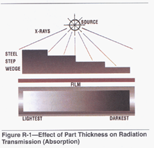
Areas of high radiation transmission, or low absorption, appear as dark areas on the developed film. Areas of low radiation transmission, or high absorption, appear as light areas on the developed film. Figure R-1 shows the effect of thickness on film darkness. The thinnest area of the test object produces the darkest area on the film because more radiation is transmitted to the film. The thickest area of the test object produces the lightest area on the film because more radiation is absorbed and thus, less is transmitted. Figure R-2 shows the effect of the material density on film darkness.


Of the metals shown in Figure R-2, lead has the highest density: 11.34 g/cm3 (0.409 lb/in3), followed in order by copper: 8.96 g/cm3 (0.323 lb/ in3); steel:
7.87 g/cm3 (0.284 lb/in3), and aluminum: 2.70 g/cm3 (0.097flb in3). With the highest density (weight per unit volume), lead absorbs the most radiation, transmits the least radiation, and thus produces the lightest film.
Lower energy, non-particulate radiation is in the form of either gamma radiation or X-rays. Gamma rays are the result of the decay of radioactive materials; common radioactive sources include Iridium 192, Cesium 137, and Cobalt 60. These sources are constantly emitting radiation and must be kept in a shielded storage container, referred to as a “gamma camera” when not in use. These containers are often shielded with lead or steel.
X-rays are man-made; they are produced when electrons, traveling at high speed, collide with matter. The conversion of electrical energy to X-radiation is achieved in an evacuated (vacuum) tube. A low current is passed through an incandescent filament to produce electrons. Application of a high potential (voltage) between the filament and a metal target accelerates electrons across this voltage differential. The action of an electron stream striking the target produces X-rays. Radiation is produced only while voltage is applied to the X-ray tube. Whether using gamma or X-ray sources, the test object is not radioactive following the test.
The following are essential elements of radiographic testing:
(1) A source of penetrating radiation, such as an X-ray machine or a radioactive isotope
(2) The object to be radiographed, such as a weldment
(3) A recording or viewing device, usually photographic (X-ray) film enclosed in a light-proof holder
(4)A qualified radiographer, trained to produce a satisfactory exposure
(5) A means to process exposed film or operate other recording media
(6) A person skilled in the interpretation of radiographs
When a test object or welded joint is exposed to penetrating radiation, some of the radiation will be absorbed, some scattered, and some transmitted through the metal to a recording medium. The variations in amount of radiation transmitted through the weld depend on the following:
(1) The relative densities of the metal and any inclusions
(2) The relative thickness of materials in the radiation path
(3) The penetrating power of the radiation source. Nonmetallic inclusions, pores, aligned cracks, and other discontinuities result in more or less radiation reaching the recording or viewing medium. The variations in transmitted radiation produce optically contrasting areas on the recording medium. The most important factor of any nondestructive weld test method is the ability of the inspector to correctly interpret the meanings of the discovered defects. Only through careful study of many radiographs exhibiting known defects can such ability be gained. The common welding faults revealed by radiographs are, in order of frequency, porosity, entrapped slag, cracks, and lack of fusion.
Porosity- Porosity usually (but not always) appears as small, black circular spots. A certain amount of porosity is allowable in a weld; how much is allowable is determined by comparing the radiograph with standard radiographs of acceptable welds.
Inclusions- Entrapped slag is readily distinguished from porosity because of its large and irregularly shaped shadows. Slag often extends parallel to a side-wall of the joint, and is easily and quickly identified. Only a very limited amount of entrapped slag is permissible in acceptable welded structures.
Slag inclusions show as dark areas in ferrous materials, but may appear as comparatively light streaks in lighter weight metals. The dark areas are created because the slag is less dense than the ferrous alloy, but may be of greater density than the lighter weight metal.
Tungsten inclusions in aluminum welds, produced by improper GTAW techniques, appear as very light areas on the film; the density of tungsten is 19.3g/cm3 (0.697 lb/in3).
Cracks- Cracks appear as dark lines in the weld. Shrinkage and stress cracks may be readily distinguished by their appearance. Shrinkage cracks are generally irregular, while stress cracks are regular and well defined
Lack of Fusion- Lack of fusion is usually easy to recognize, since it has the appearance of a thin line of slag, or a crack, close to the joint wall.
Equipment
The equipment required to perform radiographic testing begins with a source of radiation; this source can be either an X-ray machine, which requires electrical input, or a radioactive isotope which produces gamma radiation. The isotopes usually offer increased portability. Either radiation type requires film and a light-tight film holder, and an alphabet of lead letters which are used to identify the test object. Because of the high density of lead and the local increased thick- ness, these letters form light areas on the developed film. Image Quality Indicators (IQI), or penetrameters (“pennys”), are used to verify the resolution sensitivity of the test. These IQIs are usually one of two types: shim or wire. They are both specified as to material type. The shim type will have a specified thickness and included hole sizes, and the wire type will have specified diameters. Sensitivity is verified by the ability to detect a given difference in density due to the penetrameter thickness and hole diameter, or wire diameter.
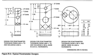
Shim penetrameters vary in thickness and hole diameters, depending on the metal thickness being radiographed. Figure R-3 shows the essential features of various penetrameter designs. When the penetrameter thickness is 0.025 in., it will have the designation of #25, for the shim thickness in mils (a #10 is 0.010 in. thick; a #50 is 0.050 in. thick). The hole diameters and positions are specified, and are noted in terms of multipliers of the individual shim thickness. The largest hole in a #25 penny is 0.100 in., and is called the “4T”hole, indicating that it is equal to four times the shim thickness. A “2T” hole (0.050 in.) is equal to two times the shim thickness. The smallest hole between the 4T and 2T hole is referred to as the “IT” hole and is exactly equal to the shim thickness, 0.025 in. These holes are used to verify resolution sensitivity, which is usually specified to be 2% of the weld thickness. However, a l% sensitivity can also be specified, but is more difficult to attain.

Film processing equipment is required to develop the exposed film and a special film viewer with intense lighting is best for interpretation of the film. Because of the potential dangers of radiation exposure to humans, radiation monitoring equipment is always required.
The major advantage of this test method is that it can detect subsurface discontinuities in all common engineering materials. A further advantage is that the developed film serves as an excellent permanent record of the test if properly stored away from excessive heat and light.
Along with these advantages are several disadvantages. One of those is the hazard posed to humans by excessive radiation exposure. Many hours of training in radiation safety are required to assure the safety of both the radiographic test personnel and other personnel in the testing vicinity. For that reason, the testing may be performed only after the test area has been evacuated, which may present scheduling problems. Radiographic testing equipment can also be very expensive, and the training periods required to produce competent operators and interpreters are somewhat lengthy. Interpretation of film should always be done by those currently certified to a minimum Level I1 per the AWS NDE Certification or ASNT’s SNT TC-1A. Another limitation of this test method is the need for access to both sides of the test object (one side for the source and the opposite for the film).
Another disadvantage of radiographic testing is that it may not detect those flaws which are considered to be more critical (e.g., cracks and incomplete fusion) unless the radiation source is preferentially oriented with respect to the flaw direction. Further, certain test object configurations (e.g., branch or fillet welds) can make both the performance of the testing and interpretation of results more difficult. However, experienced test personnel can obtain radiographs of these more difficult geometries and interpret them with a high degree of accuracy. See also X-RAY TESTING OF WELDS.