An arc welding process that uses an arc between a continuous filler metal electrode and the weld pool. The process is used with shielding from an externally supplied gas and without the application of pressure. See PULSED GAS METAL ARC WELDING and SHORT CIRCUIT GAS METAL ARC WELDING.
The basic concept of GMAW was introduced in the 1920s, but it was not until 1948 that it was made commercially available. At first it was considered to be fundamentally a high current density, small diameter, bare-metal electrode process using an inert gas for arc shielding. Its primary application was for welding aluminum. As a result, the term MIG (Metal Inert Gas) was used to describe the process and is still a common reference. The term MIG has been superseded by GMAW.
Subsequent process developments included operation at low-current densities and pulsed direct current, application to a broader range of materials, and the use of reactive gases (particularly CO2) and gas mixtures. This latter development has led to the formal acceptance of the term gas metal arc welding (GMAW) for the process, because both inert and reactive gases are used.
A variation of the GMAW process uses a tubular electrode in which metallic powders make up the bulk of the core materials (metal cored electrode). Such electrodes require a gas shield to protect the molten weld pool from atmospheric: contamination.
Metal cored electrodes are considered a segment of GMAW by the American Welding Society. Foreign welding associations may group metal cored electrodes with flux cored electrodes.
GMAW may be operated in semiautomatic, machine, or automatic modes. All commercially important metals such as carbon steel, high-strength, low-alloy steel, stainless steel, aluminum, copper, titanium, and nickel alloys can be welded in all positions with this process by choosing the appropriate shielding gas, electrode, and welding variables.
In addition to joining, the GMAW process is widely used for surfacing where an overlay weld deposit may provide desirable wear or corrosion resistance or other properties. Overlays are normally applied to carbon or manganese steels and must be carefully engineered and evaluated to assure satisfactory results.
Uses and Advantages
The uses of the process are, of course, dictated by its advantages, the most important of which are the following:
(1) It is the only consumable electrode process that can be used to weld all commercial metals and alloys.
(2) GMAW overcomes the restriction of limited electrode length encountered with shielded metal arc welding.
(3) Welding can be done in all positions, a feature not found in submerged arc welding.
(4) Deposition rates are significantly higher than those obtained with shielded metal arc welding.
(5) Welding speeds are higher than those with shielded metal arc welding because of the continuous electrode feed and higher filler metal deposition rates.
(6) Because the wire feed is continuous, long welds can be deposited without stops and starts.
(7) When spray transfer is used, deeper penetration is possible than with shielded metal arc welding, which may permit the use of smaller size fillet welds for equivalent strengths.
(8) Minimal postweld cleaning is required due to the absence of a heavy slag.
These advantages make the process particularly well suited to high production and automated welding applications. This has become increasingly evident with the advent of robotics, where GMAW has been the predominant process choice.
Limitations
As with any welding process, there are certain limitations which restrict the use of gas metal arc welding. Some of these are the following:
(1) The welding equipment is more complex, more costly, and less portable than that for SMAW.
(2) GMAW is more difficult to use in hard-to-reach places because the welding gun is larger than a shielded metal arc welding holder, and the welding gun must be close to the joint, between 10and 20 mm (3/8 and 3/4 in.), to ensure that the weld metal is properly shielded.
(3)The welding arc must be protected against air drafts that will disperse the shielding gas. This limits outdoor applications unless protective shields are placed around the welding area.
(4) Relatively high levels of radiated heat and arc intensity can result in operator resistance to the process.
Fundamentals of the Process
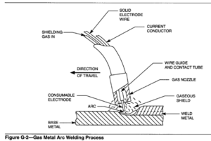
The GMAW process incorporates the automatic feeding of a continuous, consumable electrode that is shielded by an externally supplied gas. The process is
illustrated in Figure G-2. After initial settings by the operator, the equipment provides for automatic self-regulation of the electrical characteristics of the arc. Therefore, the only manual controls required by the welder for semiautomatic operation are the travel
speed and direction, and gun positioning. Given proper equipment and settings, the arc length and the current (wire feed speed) are automatically maintained.
Equipment
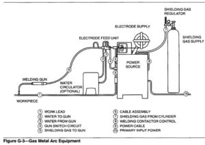
Equipment required for GMAW is shown in Figure G-3. The basic equipment components are the welding gun and cable assembly, electrode feed unit, power supply, and source of shielding gas.
The gun guides the consumable electrode and conducts the electric current and shielding gas to the work, thus providing the energy to establish and maintain the arc and melt the electrode, as well as the needed protection from the ambient atmosphere. Two
combinations of electrode feed units and power supplies are used to achieve the desirable self-regulation of arc length. Most commonly this regulation consists of a constant-potential (CP) power supply (characteristically providing an essentially flat volt-ampere curve) in conjunction with a constant-speed electrode feed unit. Alternatively, a constant-current power supply provides a drooping volt-ampere curve, and the electrode feed unit is arc-voltage controlled.
With the constant-potential/constant wire feed combination, changes in the torch position cause a change in the welding current that exactly matches the change in the electrode stick-out (electrode extension), thus the arc length remains fixed. For example, an increased stick-out produced by withdrawing the torch reduces the current output from the power supply, thereby maintaining the same resistance heating of the electrode.
In the alternative system, self-regulation results when arc voltage fluctuations readjust the control circuits of the feeder, which appropriately changes the wire feed speed. In some cases (when welding aluminum, for example), it may be preferable to deviate from these standard combinations and utilize a constant-current power source with a constant-speed electrode feed unit. This combination provides only a small degree of automatic self-regulation, and therefore requires more operator skill for semiautomatic
welding. However, some users think this combination affords a range of control over the arc energy (current) that may be important in coping with the high thermal conductivity of aluminum base metals.
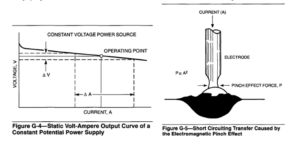
Slope. The static volt-ampere characteristic (static output) of a CP power source is illustrated in Figure (3-4.The slope of the output is the algebraic slope of the volt ampere curve and is customarily given as the voltage drop per 100amperes of current rise.
Slope has a major function in the short circuiting transfer mode of GMAW in that it controls the magnitude of the short circuit current, which is the amperage that flows when the electrode is shorted to the workpiece. In GMAW, the separation of molten drops of metal from the electrode is controlled by an electrical phenomenon called the electromagnetic pinch effect. Pinch is the magnetic “squeezing” force on a conductor produced by the current flowing through it. For short circuiting transfer, the effect is illustrated in Figure G-5.
In short circuiting transfer the amount of short circuit current is important since the resultant pinch effect determines the way a molten drop detaches from the electrode. This in turn affects the arc stability. When little or no slope is present in the power supply
circuit, the short circuit current will rise rapidly to a high level. The pinch effect will also be high, and the molten drop will separate violently from the wire. The excessive pinch effect will abruptly squeeze the metal aside, clear the short circuit, and create excessive spatter.
Inductance. When the electrode shorts to the work, the current increases rapidly to a higher level. The circuit characteristic affecting the time rate of this increase in current is inductance, usually measured in henrys. The effect of inductance is illustrated by the curves plotted in Figure G-6. Curve A is an example of a current-time curve immediately after a short circuit when some inductance is in the circuit. Curve B illustrates the path the current would have taken if there were no inductance in the circuit.
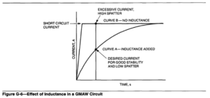
The maximum amount of pinch effect is determined by the final short circuit current level. The instantaneous pinch effect is controlled by the instantaneous
current, and therefore the shape of the current-time curve is significant. The inductance in the circuit controls the rate of current rise. Without inductance the pinch effect is applied rapidly and the molten drop will be violently “squeezed” off the electrode and cause
excessive spatter. Higher inductance results in a decrease in the short circuits per second and an increase in the “arc-on” time. Increased arc-on time makes the puddle more fluid and results in a flatter, smoother weld bead.
In spray transfer, the addition of some inductance to the power source will produce a softer arc start without affecting the steady-state welding conditions.
Power source adjustments required for minimum spatter conditions vary with the electrode material and diameter. As a general rule, higher short circuit currents and higher inductance are needed for larger diameter electrodes. Power sources are available with fixed, stepped, or continuously adjustable inductance levels.
Metal Transfer Mechanisms
The characteristics of the GMAW process are best described in terms of the three basic means by which metal is transferred from the electrode to the work:
(1) Short circuiting transfer
(2) Globular transfer
(3) Spray transfer
The type of transfer is determined by a number of factors, the most influential of which are the
following:
(1) Magnitude and type of welding current
(2) Electrode diameter
(3) Electrode composition
(5) Shielding gas
(1)Magnitude and type of welding current are affected by (1) type of base metal, (2) electrode
(2) Electrode diameter composition, (3) welding position, and (4) quality
(3) Electrode composition requirements. Thus, there is no single set of parameters
(4)Electrode extension that gives optimum results in every case.
(5)Shielding gas Welding Current
Process Variables
The following are some of the variables that affect weld penetration, bead geometry, and overall weld quality:
(1) Welding current (electrode feed speed)
(2) Polarity (DCEN or DCEP)
(3) Arc voltage (arc length)
(4)Travel speed
(5) Electrode extension (stick-out)
(6) Electrode orientation (trail or lead angle)
(8) Electrode diameter
(9) Shielding gas composition and flow rate
Knowledge and control of these variables is essential to produce welds of satisfactory quality consistently. These variables are not completely independent, and changing one generally requires changing one or more of the others to produce the desired results. Considerable skill and experience are needed to select optimum settings for each application. The optimum values are affected by (1) type of base metal, (2) electrode composition, (3) welding position, and (4) quality requirements. Thus, there is no single set of parameters that gives optimum results in every case.
When all other variables are held constant, the welding amperage varies with the electrode feed speed or melting rate in a nonlinear relation, As the electrode feed speed is varied, the welding amperage will vary in a like manner if a constant-voltage power source is used. This relationship of welding current to wire feed speed for carbon steel electrodes is shown in Figure G-7.
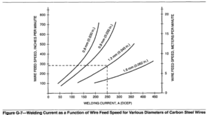
At the low-current levels for each electrode size, the curve is nearly linear. However, at higher welding currents, particularly with small diameter electrodes, the
curves become nonlinear, progressively increasing at a higher rate as welding amperage increases. This is attributed to resistance heating of the electrode extension beyond the contact tube.
With all other variables held constant, an increase in welding current (electrode feed speed) will result in the following:
(1) An increase in the depth and width of the weld penetration
(2) An increase in the deposition rate
(3) An increase in the size of the weld bead Pulsed spray welding is ii variation of the GMAW process in which the current is pulsed to obtain the advantages of the spray mode
of metal transfer at aver- age currents equal to or less than the globular-to-spray transition current.
Since arc force and deposition rate are exponentially dependent on current, operation above the transition current often makes the arc forces uncontrollable in the vertical and overhead positions. By reducing the average current with pulsing, the arc force and deposition rates can both be reduced, allowing welds to be made in all positions and in thin sections.
With solid wires, another advantage of pulsed power welding is that larger diameter wires, i.e., 1.6mm (1/16 in.) can be used. Although deposition rates are generally no greater than those with smaller diameter wires, the advantage is in the lower cost per unit of metal deposited. There is also an increase in deposition efficiency because of reduced spatter loss.
With metal cored wires, pulsed power produces an arc that is less sensitive to changes in electrode extension (stickout) and voltage compared to solid wires. Thus, the process is more tolerant of operator guidance fluctuations. Pulsed power also minimizes spatter from an operation already low in spatter generation.
The term polarity is used to describe the electrical connection of the welding gun with relation to the terminals of a direct current power source. When the gun power lead is connected to the positive terminal, the polarity is designated as direct current electrode
positive (DCEP), arbitrarily called reverse polarity. When the gun is connected to the negative terminal, the polarity is designated as direct current electrode negative (DCEN), originally called straight polarity.
The vast majority of GMAW applications use direct current electrode positive (DCEP). This condition yields a stable arc, smooth metal transfer, relatively low spatter, good weld bead characteristics, and greatest depth of penetration for a wide range of welding currents.
Direct current electrode negative (DCEN) is seldom used because axial spray transfer is not possible without modifications that have had little commercial acceptance. DCEN has a distinct advantage of high melting rates that cannot be exploited because the
transfer is globular. With steels, the transfer can be improved by adding a minimum of 5% oxygen to the argon shield (requiring special alloys to compensate for oxidation losses) or by treating the wire to make it thermionic (adding to the cost of the filler metal). In both cases, the deposition rates drop, eliminating the only real advantage of changing polarity. However, because of the high deposition rate and reduced penetration, DCEN has found some use in surfacing applications.
Attempts to use alternating current with the GMAW process have generally been unsuccessful. The cyclic wave form creates arc instability due to the tendency of the arc to extinguish as the current passes through the zero point. Although special wire surface treatments have been developed to overcome this problem, the expense of applying them has made the technique uneconomical.
Arc voltage and arc length are terms that are often used interchangeably. It should be pointed out, however, that they are different even though they are related. With GMAW, arc length is a critical variable that must be carefully controlled. For example, in the spray-arc mode with argon shielding, an arc that is too short experiences momentary short circuits. They cause pressure fluctuations which pumps air into the arc stream, producing porosity or embrittlement due to absorbed nitrogen. Should the arc be too long, it tends to wander, affecting both the penetration and surface bead profiles. A long arc can also disrupt the gas shield.
With all variables held constant, arc voltage is directly related to arc length. Even though the arc length is the variable of interest and the variable that should be controlled, the voltage is more easily monitored. Because of this, and the normal requirement that
the arc voltage be specified in the welding procedure, it is the term that is more commonly used.
The electrode extension is the distance between the end of the contact tube and the end of the electrode. An increase in the electrode extension results in an increase in its electrical resistance. Resistance heating in turn causes the electrode temperature to rise, and results in a small increase in electrode melting rate. Overall, the increased electrical
resistance produces a greater voltage drop from the contact tube to the work. This is sensed by the power source, which compensates by decreasing the current. That immediately reduces the electrode melting rate, which then lets the electrode shorten the physical arc length. Thus, unless there is an increase in the voltage at the welding machine, the filler metal will be deposited as a narrow, high-crowned weld bead.
The desirable electrode extension is generally from 6 to 12 mm (1/4 to 1/2 in.) for short circuiting transfer and from 12 to 25 mm (1/2 to 1 in.) for other types of metal transfer.
Most spray type GMAW is done in the flat or horizontal positions, while at low-energy levels, pulsed and short circuiting GMAW can be used in all positions. Fillet welds made in the flat position with spray transfer are usually more uniform, less likely to have unequal legs and convex profiles, and are less susceptible to undercutting than similar fillet welds made in the horizontal position.
To overcome the pull of gravity on the weld metal in the vertical and overhead positions of welding, small diameter electrodes are usually used, with either short circuiting metal transfer or spray transfer with pulsed direct current. Electrode diameters of 1.1 mm (0.045 in.) and smaller are best suited for out-of-position welding. The low-heat input allows the molten pool to freeze quickly. Downward welding progression is usually effective on sheet metal in the vertical position.
When welding is done in the flat position, the inclination of the weld axis with respect to the horizontal plane will influence the weld bead shape, penetration, and travel speed. In flat position circumferential welding, the work rotates under the welding gun and inclination is obtained by moving the welding gun in either direction from top dead center.
Consumables
In addition to equipment components, such as contact tips and conduit liners that wear out and have to be replaced, the process consumables in GMAW are electrodes and shielding gases. The chemical composition of the electrode, the base metal, and the shielding gas determine the weld metal chemical composition. This weld metal composition, in turn, largely determines the chemical and mechanical properties of the weldment. The following are factors that influence the selection of the shielding gas and the welding electrode:
(1) Base metal
(2) Required weld metal mechanical properties
(3) Base metal condition and cleanliness
(4) Type of service or applicable specification requirement
(5) Welding position
(6) Intended mode of metal transfer
Electrodes
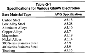
The electrodes (filler metals) for gas metal arc welding are covered by various AWS filler metal specifications. Other standards writing societies also publish filler metal specifications for specific applications. For example, the Aerospace Materials specifications are written by SAE, and are intended for aerospace applications. The AWS specifications, designated as A5.XX standards, and a listing of GMAW electrode specifications are shown in Table G-1. They define requirements for sizes and tolerances, packaging, chemical composition, and sometimes mechanical properties. The AWS also publishes Filler Metal Comparison Charts, in which manufacturers may show their trade name for each of the filler metal classifications.
Shielding Gases
The primary function of the shielding gas is to exclude the atmosphere from contact with the molten weld metal. This is necessary because most metals, when heated to their melting point in air, exhibit a strong tendency to form oxides and, to a lesser extent, nitrides. Oxygen will also react with carbon in molten steel to form carbon monoxide and carbon dioxide. These varied reaction products may result in weld
deficiencies, such as trapped slag, porosity, and weld metal embrittlement. Reaction products are easily formed in the atmosphere unless precautions are taken to exclude nitrogen and oxygen.
In addition to providing a protective environment, the shielding gas and flow rate also have a pronounced effect on the following:
(1) Arc characteristics
(2) Mode of metal transfer
(3) Penetration and weld bead profile
(4) Speed of welding
(5) Undercutting tendency
(6) Cleaning action
(7) Weld metal mechanical properties
Reference: American Welding Society. Welding Handbook, 8th Edition, Vol. 2, Welding Processes. Miami, Florida: American Welding Society, 1991.