A resistance welding process that produces coalescence over the entire area of faying surfaces or progressively along a butt joint by the heat obtained from the resistance to the flow of welding current through the area where those sur$aces are in contact. Pressure is used to complete the weld. See Figure U-3.
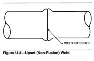
WELD INTERFACE
Principles of Operation. With this process, welding is essentially done in the solid state. The metal at the joint is resistance-heated to a temperature where recrystallization can rapidly take place across the faying surfaces. A force is applied to the joint to bring the faying surfaces into intimate contact and then upset the metal. Upset hastens recrystallization at the interface and, at the same time, some metal is forced outward from this location. This tends to purge the joint of oxidized metal.
Process Variations
Upset welding has two variations:
(1) Joining two sections of the same cross section end-to-end (butt joint)
(2) Continuous welding of butt joint seams in roll formed products such as pipe and tubing.
The first variation can also be accomplished by flash welding and friction welding. The second variation is also done with high-frequency welding.
Butt Joints. A wide variety of metals in the form of wire, bar, strip, and tubing can be joined end-to-end by upset welding. These include carbon steels, stainless steels, aluminum alloys, brass, copper, nickel alloys, and electrical resistance alloys.
Sequence of Operations. The essential operational steps to produce an upset welded butt joint are as follows:
(1)Load the machine with the parts aligned end-to-end
(2) Clamp the parts securely
(3) Apply a welding force
(4) Initiate the welding current
(5)Apply an upset force
(6) Shut off the welding current
(7) Release the upset force
(8) Unclamp the weldment
(9) Return the movable platen and unload the weldment(s).
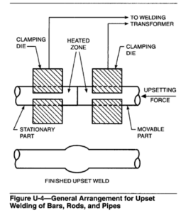
The general arrangement for upset welding is shown in Figure U-4. One clamping die is stationary and the other is movable to accomplish upset. Upset force is applied through the moveable clamping die or a mechanical backup, or both.
Joint Preparation. For uniform heating, the faying surfaces should be flat, comparatively smooth, and perpendicular to the direction of the upsetting force. Prior to welding, they should be cleaned to remove any dirt, oil, oxidation, or other materials that will impede welding.
The contact resistance between the faying surfaces is a function of the smoothness and cleanliness of the surfaces and the contact pressure. This resistance varies inversely with the contact pressure, provided the other factors are constant. As the temperature at the joint increases, the contact resistance changes, but it finally becomes zero when the weld is formed. Upset welding differs from flash welding in that no flashing takes place at any time during the welding cycle.
Generally, force and current are maintained throughout the entire welding cycle. The force is kept low at first to promote high initial contact resistance between the two parts. It is increased to a higher value to upset the joint when the welding temperature is reached. After the prescribed upset is accomplished, the welding current is turned off and the force is removed.
Equipment. Equipment for upset welding is generally designed to weld a particular family of alloys, such as steels, within a size range based on cross-sectional area. The mechanical capacity and electrical characteristics of the machine are matched to that application. Special designs may be required for certain aluminum alloys to provide close control of the upset force.
Electric current for heating is provided by a resistance welding transformer. It converts line power to low-voltage, high-current power. No-load secondary voltages range from about 0.4 to 8 V. Secondary current is controlled by a transformer tap switch or by electronic phase shift.
Basically, an upset welding machine has two platens, one of which is stationary and the other movable. The clamping dies are mounted on these platens. The clamps operate either in straight line motion or through an arc about an axis, depending upon the application. Force for upset butt welding is produced generally by a mechanical, pneumatic, or hydraulic system.
Heat Balance. The upset process is generally used to join together two pieces of the same alloy and same cross-sectional geometry. In this case, heat balance should be uniform across the joint. If the parts to be welded are similar in composition and cross section but of unequal mass, the part of larger mass should project from the clamping die somewhat farther than the other part. With dissimilar metals, the one with higher electrical conductivity should extend farther from the clamp than the other. When upset welding large parts that do not make good contact with each other, it is sometimes advantageous to interrupt the welding current periodically to allow the heat to distribute evenly into the parts.
Applications. Upset welding is used in wire mills and in the manufacture of products made from wire. In wire mill applications, the process is used to join wire coils to each other to facilitate continuous processing. Upset welding is also used to fabricate a wide variety of products from bar, strip, and tubing stock. Wire and rod from 12.7 to 31.8 mm (0.05 to 1.25 in.) diameter can be upset welded.
Weld Quality. Butt joints can be made that have about the same properties as the unwelded base metal. With proper procedures, welds made in wires are difficult to locate after they have passed through a subsequent drawing process. In many instances, the welds are then considered part of the continuous wire.
Upset welds may be evaluated by tension testing. The tensile properties are compared to those of the base metal. Metallographic and dye penetrant inspection techniques are also used.
A common method for evaluating a butt weld in wire is a bend test. A welded sample is clamped in a vise with the weld interface located one wire diameter from the vise jaws. The sample then is bent back and forth until it breaks in two. If the fracture is through the weld interface and shows complete fusion, or if it occurs outside the weld, the weld quality is considered satisfactory.
Continuous Upset Butt Welding
In the manufacture of welded pipe or tubing by continuous upset welding, coiled strip is fed into a set of forming rolls. These rolls progressively form the strip into a cylindrical shape. The edges to be joined approach each other at an angle and culminate in a longitudinal V at the point of welding. A wheel electrode contacts each edge of the tube a short distance from the apex of the V. Current from the power source travels from one electrode along the adjacent edge to the apex, where welding is taking place, and then back along the other edge to the second electrode. The edges are resistance-heated to welding temperature by this current. The hot edges are then upset together by a set of pinch rolls to accomplish the weld.
Equipment. Figure U-5 shows a typical tube mill that uses upset welding to join the longitudinal seam. Figure U-5 (A) shows the steel strip entering the strip
guide assembly and the first stages of the forming section. The heat regulator, located behind the forming section, can be adjusted either manually or by phase-shift heat control. Figure U-5 (B) shows a rotary type oil-cooled welding transformer. This welding equipment includes a dressing tool assembly for dressing the welding electrodes without removing them from the welding machine, and a scarfing tool assembly that removes the upset metal after welding. The welded tube then enters the straightening and sizing section, shown in Figure U-5 (C). Following this, the tubing is cut to the desired length.
Welding can be done using either a-c or d-c power. Alternating-current machines may be operated on either 60 Hz single-phase power or on power of higher frequency produced by a single-phase alternator. Direct-current machines are powered by a three-phase transformer-rectifier unit.
Welding Procedures. As the formed tube passes through the zone between the electrodes and the pinch rolls, there is a variation in pressure across the joint. If no heat were generated along the edges, this pressure would be maximum at the center of the squeeze rolls. However, since heat is generated in the metal ahead of the squeeze roll center line, the metal gradually becomes plastic and the point of initial edge contact is slightly ahead of the squeeze roll axes. The point of maximum upset pressure is somewhat ahead of the
squeeze roll centerline.
The current across the seam is distributed in inverse proportion to the resistance between the two electrodes. This resistance, for the most part, is the contact resistance between the edges to be welded. Pressure is effective in reducing this contact resistance. As the temperature of the joint increases, the electrical resistance will increase and the pressure will decrease. A very sharp thermal gradient caused by the resistance heating at the peaks of the a-c cycle produces a “stitch effect.” The stitch is normally of circular cross section, lying centrally in the weld area and parallel to the line of initial closure of the seam edges. It is the hottest portion of the weld. The stitch area is molten while the area between stitches is at a lower temperature. The patches of molten metal are relatively free to flow under the influence of the motor forces (current and magnetic flux) acting on them. Consequently, they are ejected from the stitch area. If the welding heat is excessive, too much metal is ejected and pinhole leaks may result. With too little heat, the individual stitches will not overlap sufficiently, resulting in an interrupted weld.
The longitudinal spacing of the stitches must have some limit. The spacing is a function of the power frequency and the travel speed of the tube being welded. With 60 Hz power, the speed of welding should be limited to approximately 0.45 m/sec (90 ft/min). To weld tubing at higher speeds than this requires welding power of higher frequency.
It is desirable to close the outside corners of the edges first as the formed tube moves through the machine so that the stitches will be inclined forward. This condition is known as an inverted V. The advantages of using an inverted V are twofold: (1)the angle deviation from the vertical reduces the forces tending to expel any molten metal in the joint, and (2) the major portion of the solid upset metal is extruded to the outside where it is easily removed. The tubing is normally formed so that the included angle of the V is about 5 to 7″. See also HIGH-FREQUENCY UPSET WELDING and INDUCTION UPSET WELDING.