A nondestructive test (NDT) method in which beams of high-frequency sound waves are introduced into a test object to detect and locate internal discontinuities. A sound beam is directed into the test object on a predictable path, and is reflected at interfaces or other interruptions in material continuity. The reflected beam is detected and analyzed to define the presence and location of discontinuities.
The detection, location and evaluation of discontinuities is possible because (1) the velocity of sound through a given material is nearly constant, making distance measurements possible, and (2) the amplitude of the reflected sound pulse is nearly proportional to the size of the reflected discontinuity. Ultrasound wave is electronically collected and presented on a cathode ray tube (CRT) screen for evaluation by a qualified and certified ultrasound technician.
Ultrasonic testing can be used to detect cracks, laminations, shrinkage cavities, pores, slag inclusions, incomplete fusion or bonding, incomplete joint penetration, and other discontinuities in weldments and brazements. With proper techniques, the approximate position and depth of the discontinuity can be determined, and in some cases, the approximate size of the discontinuity can be determined.
Advantages
The principal advantages of UT compared to other NDT methods are the following:
(1) Discontinuities in thick sections can be detected.
(2) Relatively high sensitivity to small discontinuities is exhibited.
(3) Depth of internal discontinuities can be determined; size and shape of discontinuities can be estimated.
(4) Adequate inspections can be made from one surface.
(5) Equipment can be moved to the job site.
(6) Process is nonhazardous to personnel or other equipment.
Limitations
The following limitations apply to ultrasonic testing:
(1) Set-up and operation require trained and experienced technicians, especially for manual examinations.
(2) Weldments that are rough, irregular in shape, very small, or thin are difficult or impossible to inspect; this includes fillet welds.
(3) Discontinuities at the surface are difficult to detect.
(4) A coupler is needed between the sound transducers and the weldment to transmit the ultrasonic wave energy.
(5) Reference standards are required to calibrate the equipment and to evaluate the size of discontinuities.
(6) Reference standards should describe the item to be examined with respect to design, material specifications, and heat treatment condition.
Equipment
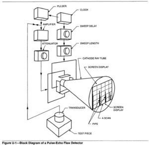
A block diagram of a pulse-echo flaw detector is shown in Figure U-1. Most ultrasonic testing systems use the following basic components:
(1) An electronic signal generator (pulser) that produces bursts of alternating voltage.
(2) A sending transducer that emits a beam of ultrasonic waves when alternating voltage is applied. The sound wave frequencies used are between 1 and 6 MHz, which are beyond the audible range. Most weld testing is performed at 2.25 MHz. Higher frequencies, Le., 5 MHz, will produce small, sharp sound beams useful in locating and evaluating discontinuities in thin wall weldments.
(3) A coupler to transmit the ultrasonic energy from the transducer to the test piece and vice versa.
(4) A receiving transducer to convert the soundwaves to alternating voltage. This transducer may becombined with the sending transducer.
(5) An electronic device to amplify and demodulate or otherwise change the signal from the receiving transducer.
(6) A display or indicating device to characterize or record the output from the test piece.
(7)An electronic timer to control the operation.
There are three basic modes of propagating sound through metals: longitudinal, (sometimes called straight or compressional), transverse (also called shear wave), and surface waves (sometimes referred to as Rayleigh waves). In the longitudinal and transverse modes, waves are propagated by the displacement of successive atoms or molecules in the metal.
Longitudinal wave ultrasound is generally limited in use to detecting inclusions and lamellar-type discontinuities in base metal. Transverse wave ultrasound is most valuable in the detection of weld discontinuities because of its ability to furnish three-dimensional coordinates for discontinuity locations, orientations, and characteristics. The sensitivity of shear waves is also about double that of longitudinal waves for the same frequency and search unit size.
The zones in the base metal adjacent to a weld should be tested with longitudinal waves first, to ensure that the base metal does not contain discontinuities that would interfere with shear wave evaluation of the weld.
In the third mode, surface waves are propagated along the metal surface, similar to waves on the surface of water. These surface waves have little movement below the surface of a metal, therefore they are not used for examination of welded and brazed joints.
Coupling- A liquid material is used for transmission of ultrasonic waves into the test object. Some of the more common coupling agents are water, light oil, glycerine, and cellulose gum powder mixed with water.
A weldment must be smooth and flat to allow intimate coupling. Weld spatter, slag, and other irregularities should be removed. Depending on the testing technique, it may be necessary to remove the weld reinforcement.
Calibration- Ultrasonic testing is basically a comparative evaluation. The horizontal (time) and the vertical (amplitude) dimensions on the CRT screen of the test unit are related to distance and size, respectively. It is necessary to establish a zero starting point for these variables, and to calibrate an ultrasonic unit to a basic standard before use.
Various test blocks are used to assist in calibration of the equipment. Known reflecting areas can simulate typical discontinuities. Notches substitute for surface cracks, side-drilled holes for slag inclusions or internal cracks, and angulated flat-bottomed holes for small areas of incomplete fusion. The test block material must be similar in acoustic qualities to the metal being tested.
The International Institute of Welding (IIW) test block is widely used as a calibration block for ultrasonic testing of steel welds. This block and other test blocks are used to calibrate an instrument for sensitivity, resolution, linearity, angle of sound propagation, and distance and gain calibrations.
Standard test blocks are shown in ASTM E164, Standard Practice for Ultrasonic Contact Exarnination of Weldrnents, latest edition, West Conshohocken, Pennsylvania: American Society for Testing and Materials.
Test Procedures- Most ultrasonic testing of welds is done following a specific code or procedure. An example of such a procedure is that contained in AWS D1.I, Structural Welding Code-Steel for testing groove welds in structures.
ASTM E164, Standard Practice for Ultrasonic Contact Examination of Weldments covers examination of specific weld configurations in wrought ferrous and aluminum alloys to detect weld discontinuities. Procedures for calibrating the equipment and appropriate calibration blocks are included. Other ASTM standards cover testing procedures with various ultrasonic inspection methods for inspection of pipe and tubing.
Procedures for UT of boiler and pressure vessel components are given in ASME Boiler and Pressure Vessel Code, Section V Nondestructive Examination. Section XI, Insewice Inspection Requirements for Nuclear Power Plants, gives methods for locating, sizing, and evaluating discontinuities for continuing service life and fracture mechanics analysis.
Operator Qualifications- The reliability of ultrasonic examination depends greatly on the interpretive ability of the ultrasonic testing technician. In general, UT requires more training and experience than the other nondestructive testing methods, with the possible exception of radiographic testing. Many critical variables are controlled by the operators. For this reason, most standards require ultrasonic technicians to meet the requirements of ASNT-TC- 1A, Personnel Qualification and Certification in Nondestructive Testing.
Reporting- Careful tabulation of information in a report form is necessary for a meaningful test. Reporting requirements are included in ANSUAWS D1.1, Structural Welding Code-Steel. The welding inspector should be familiar with the kinds of data that must be recorded and evaluated so that a satisfactory determination of weld quality can be obtained. Standards for testing have been published by the American Society for Nondestructive Testing, the American Society of Mechanical Engineers, and the American Welding Society.