A group of processes in which finely divided metallic or nonmetallic surfacing materials are deposited in a molten or semimolten condition on a substrate to form a thermal spray deposit. The surfacing material may be in the form of powdel; rod, cord, or wire. See ARC SPRAYING, FLAME SPRAYING, and PLASMA SPRAYING.
Thermal spraying can be used to form a coating on metals, ceramics, glass, most plastics, and wood. It is used extensively in the manufacture of original equipment components. For example, the aerospace industry has developed hundreds of applications, including air seals and wear-resistant surfaces to prevent fretting and galling at elevated temperatures. In addition, marine, mining, food, automotive, petroleum, electrical power generation, thermal processing, chemical processing and electronic applications use thermally sprayed coatings to achieve results that no substrate by itself can provide.
The surfacing is applied with a thermal spraying gun, which generates the necessary heat by using combustible gases or an electric arc. As the materials are heated, they change to a plastic or molten state, and are accelerated by a compressed gas. The particles, in a confined stream, are conveyed to a substrate. The particles strike the surface, flatten, and form thin platelets (splats) that conform and adhere to the irregularities of the prepared surface and to each other. As the sprayed particles impinge on the substrate, they cool and build up, particle by particle, into a lamellar structure; thus a coating is formed.
Process Variations
The basic variations of the thermal spraying processes occur in the spray materials used, the method of heating, and the method of propelling the materials to the substrate.
Spray Materials. The spray materials used are in the form of wire, rod, cord (a continuous length of plastic tubing), or powder. Cord spraying is primarily used in Europe. Many metals, oxides, cermets, and intermetallic compounds, some organic plastics, and certain glasses can be deposited by one or more of the various processes.
Processes. Thermal spraying processes can be categorized under two basic groups, according to the methods of heat generation. See Table T- 4.Group 1 uses combustible gases as the heat source. Group 2 uses electric power as the heat source, such as plasma, electric arc, and induction plasma. Consumables used in Group 2 are in the powder or wire form. Additional heat is generated at impact during hypersonic flame spraying, as the spray material gives up its kinetic energy.
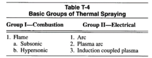
Group I-Combustion
Subsonic Flame Spraying. In subsonic flame spraying, the spray material is fed into and melted by an oxyfuel gas flame. Whether the material is in the form of wire, rod or powder, molten particles are propelled onto the substrate by the force of the flame.
A wide variety of materials in these forms can be sprayed with the flame. Materials that cannot be melted with an oxyfuel gas flame, and those that burn or become severely oxidized in the oxyfuel flame, cannot be flame sprayed.
Flame spray accessories in the form of air jets and air shrouds are available to change the flame characteristics. These accessories can be used to adjust the shape of the flame and the velocity of the sprayed materials.
Materials are deposited in multiple layers, each of which can be as thin as 130 pm (0.0005 in.) per pass. The total thickness of material deposited will depend upon several factors including:
(1) Type of surfacing material and its properties
(2) Condition of the workpiece material, including geometry
(3) Service requirements of the coated product
(4) Post-spray treatment of the coated product
Hypersonic Flame Spraying. Detonation and continuous-flame guns are two types of hypersonic spray guns.
The detonation gun operates on principles significantly different from other flame spray methods. This method repeatedly heats and projects charges of powder onto a substrate by rapid successive detonations of an explosive mixture of oxygen and acetylene in the gun chamber.
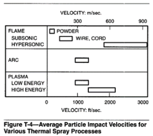
The continuous-flame hypersonic guns used in the United States use a propylene-oxygen flame. The powder is brought to the torch using a nitrogen carrier. The torch is designed to confine the powder in the center of the flame. The particles leave the gun at velocities generally in excess of mach 4. This speed is far greater than achieved in most other spray methods. Particle impact velocities for various thermal spray processes are shown in Figure T-4. The kinetic energy released by impingement upon the substrate contributes additional heat that promotes bonding, high density, and appreciable hardness values.
Group Il-Electric
Arc Spraying. The spray materials used with arc spraying, commonly called electric arc spniying, are metals and alloys in wire form, and powders contained in a metal sheath (cored wire). Two continuously fed wires are melted by an arc operating between them.
The molten metal is atomized and propelled onto the substrate by a high-velocity gas jet, usually air. Recent work has been done using other gases. This method is restricted to spraying consumables that car1 be produced in continuous wire form.
Plasma Spraying. Plasma spraying is a thermal spraying process in which a nontransferred plasma arc gun is used to create an arc plasma that melts and propels the surfacing material to the substrate.
The term nontrunsferred arc means that the plasma arc is contained within the gun, and that the substrate is not part of the electric circuit. The arc is maintained between a tungsten cathode and a constricting nozzle which serves as the anode. An inert gas or a reducing gas, under pressure, enters the annular space between the anode and cathode, where it becomes ionized, producing temperatures up to 17 000°C (30 000°F). The hot plasma gas passes through the nozzle as a high-velocity jet. The surfacing material, in powder form, is injected into the hot gas stream, where it becomes molten and is propelled onto the substrate.
Plasma Transferred Arc (PTA). This process is a combination of welding and thermal spraying processes. Powder is introduced into the plasma arc stream from where it is melted and conveyed to the workpiece. The emitted spray forms a molten puddle on the substrate, which cools and solidifies as a parent metal dilution (weldment). As compared to a thermal spraying deposit, a FTA deposit is generally more localized, denser, and metallurgically bonded to the base. The selection of coating materials and suitable substrates is limited.
Vacuum Plasma Spraying. Vacuum spraying is a variation of plasma spraying which is performed in a vacuum chamber. The advantage of the process is the elimination of oxides from the deposit. This is especially advantageous in aircraft engine applications.
The cost of this apparatus is about ten times that of standard plasma spray equipment. Operating costs are also higher.
Induction Coupled Plasma Spraying. Induction coupled plasma equipment is used to create an ultra high temperature arc region 50 mm (2 in.) in diameter by 150 mm (6 in.) long, into which powders are injected. The powder is heated along a substantially longer path than that within a comparable plasma spray gun. The longer powder residence time makes possible the use of larger particles, assures the melting of the particles, and results in a more consistent sprayed coating.
Because of the size of the equipment, this system has limited torch movement and portability.
Procedures for Sprayed Coatings
Success in the use of thermally sprayed coatings relies on careful adherence to specific process procedures. This is a basic rule of thermal spraying, and deviation from the standards for a particular application, or inattention to detail, especially preparation, will produce an unreliable result.
Sprayed coating systems have four basic components: substrate type, bond coats as necessary, coating structure, and finish.
Substrates. Substrates on which the thermally sprayed coatings are applied include metals, oxides, ceramics, glass, most plastics, and wood. All spray materials cannot be applied to all substrates, since some require special techniques or are temperature sensitive.
Substrate preparation is required for every thermal spraying process, and is virtually the same for each process. Two important steps are:
(1) Cleaning the surface to eliminate contamination that will inhibit the bonding of the coating to the substrate.
(2) Roughening the substrate surface to create minute asperities or irregularities (anchor teeth), which provide a greater effective surface area to enhance coating adhesion and bond strength.
Bond Coats. Certain materials adhere to clean, smooth surfaces forming strong coating-to-substrate bonds, over a wide range of conditions. A thm layer of bonding material serves as an anchor for subsequent applied coating layers. Bond coatings are particularly applicable to substrates too thin or too hard to be prepared by abrasive roughening methods. Bond coatings are used extensively as a substrate for ceramic materials. Bond coatings of nickel, chromium, stainless steel, or the corrosion resistant alloys are applied in thicknesses of 0.05 to 0.33 mm (0.002 to 0.013in.) or more. The bond coating provides a flexible and adherent substrate for ceramic deposits. The bond between the coating and the substrate may be mechanical or metallurgical. Adhesion is influenced by a combination of (1) coating material, (2) spray particle size, (3) substrate condition and geometry, (4)degree of surface roughness, (5)surface cleanliness, (6) surface temperature before, during, and after spraying, (7) particle impact velocity, (8) type of base material, and (9) spray angle.
Coating Structure. The deposited structure and chemistry of coatings sprayed in ambient air are different from those of the same material in the wrought or pre-sprayed form.
The differences in structure and chemistry are due to the incremental nature of the coating, and its reaction with the process gases and the atmosphere surrounding the coating material while in the molten state. For example, when air or oxygen is used as the process gas, oxides of the spray material are formed while the particles are in transit and become a part of the coating.
Metal coatings tend to be porous and brittle, and to differ in hardness from the original consumable material.The“as-sprayed”structures of coatings will be similar in their lamellar nature, but will exhibit varying characteristics, depending on the particular spraying process used, process variables, techniques employed, and the nature of the spray material applied.
The coating density will vary with the particle velocity, the heat source temperature of the spray process, and the amount of air used. A listing of heat source temperatures is shown in Table T-5. The density also varies with the typeo f powder, its mesh size, spray rate, standoff distance, and method of injection.
The nature of the ‘bond in the “as-sprayed” condition can be modified by post spray thermatlr eatment. Modification is by diffusion, chemical reaction, or both, between the coating and the substrate.
The thermal spraying processes and related equipment in commercial use canb e divided into two basic methods of deposition: combustion and electric heating.
Combustion
Thermal spraying which utilizes the heat from a chemical reaction is known as combustion, gas, or flame spraying. Any substance which does not sublime and which meltsa t temperatures less than 2760°C (5000°F) may be flame sprayed. The materials used are metals and alloys in the form of wire, cord, powder, and ceramics as powder, cord, or rod.
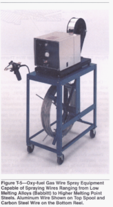
Wire and Rod. The equipment for flame spraying wire and rod is similar to that shown in FigureT-5. A cross section of a typical wire thermal spraying gun is shown in FigureT-6.
The feedstock material is drawn by drive rolls into the rear of the gun. The rolls are powered by an electric motor, or an air turbine. The feedstock proceeds through the nozzle where it is melted by a coaxial flame of burning gas.
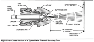
One of the following fuel gases may be combined with oxygen for use in flame spraying: acetylene, methylacetylene-propadiene stabilized (MPS), propane, hydrogen, or natural gas. Acetylene is widely used because higher flame temperatures are attainable.
See Table T-5. ‘In many cases lower temperature flames can be used to economic advantage. A fuel gas flame is used for melting only, and not for propelling or conveying the coating material. To accomplish spraying, the flame is surrounded with a stream of compressed gas, usually air, which atomizes the molten material and propels it onto the substrate. For special applications inert gas may be used.
Powder. Powder flame spraying guns are lighter and more compact than other types of thermal spraying equipment. Due to lower particle velocities and temperatures obtained, the coatings produced have lower adhesive strength, lower overall cohesive strength, and higher porosity than coatings produced by other spray processes.
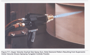
The powder feedstock may be pure metal, an alloy, a composite, a carbide, a ceramic, or any combination of these. The process is used to apply “self fluxing” metallic alloy coatings. These materials contain boron and silicon, which serve as fluxing agents, and oxida- tion is minimized. Feedstock is stored in a hopper which may be integrated with the gun or connected to it. A small amount of gas is diverted to carry the powder from the hopper into the oxyfuel gas stream, where the powder is melted and carried by the flame onto the substrate. The typical powder feeding mechanism incorporates a container and metering device which regulates the feed rate of the material into the carrier gas stream. A hyper-velocity oxyfuel gas powder spray gun is shown in Figure T-7.
Fusion or metallurgical bonding to a metal substrate is accomplished by heating the deposit to its melting temperature range. The fusing temperature is usually in excess of 1040°C (1900”F), and is accomplished with any heating source such as a flame, induction coil, or a furnace.
Variations in the powder flame spraying process include compressed gas to feed powder to the flame, additional air jets to accelerate the molten particles, a remote powder feeder with an inert gas to convey powder through a pressurized tube into the gun, and devices for high-speed powder acceleration at atmospheric pressure. Such refinements tend to improve flow rate, and sometimes to increase particle velocity, which enhances bond strength and coating density.
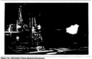
Oxygen Detonation Gun. The detonation gun is different from other combustion spraying devices. It uses the energy of explosions of oxygen-acetylene mixtures, rather than a steady flame, to blast powdered particles onto the surface of the substrate. The resulting deposit is extremely hard, dense, and tightly bonded.
The detonation gun, shown in Figure T-8, consists of a long barrel into which a mixture of oxygen, fuel gas, and powdered coating material, suspended in nitrogen, is introduced. The gas mixture is ignited by an electric spark several times per second, creating a series of controlled detonation waves (flame fronts) which accelerate and heat the powder particles as they move down the barrel. Exit particle velocities of approximately 760 dsec (2500 ft/sec) are produced. After each ejection of powder, nitrogen purges the unit priorto successive detonations. Multiple detonations per second build up the coating to the specified thickness.
Temperatures above 3315°C (6000°F) are achieved within the detonation gun, while the substrate temperature is maintained below 150°C (300°F) by a carbon dioxide cooling system.
Coating thicknesses range between 0.05 and0.50 mm (0.002 and 0.02 in.). The process produces a sound level in excess of 150 decibels, and is housed in a soundproof room. The actual coating operation is completely automatic and remotely controlled. The high particle impingement velocity results in a strong bond with the substrate. Excellent finishes are achievable, and the porosity content of the coating is low.
Electrical Heating
Wire Arc Process. The wire arc spray process uses anarc between two consumable wires (feedstock). They are kept insulated from each other and automati- cally advance to meet at a point within an atomizing gas stream. A potential difference of 18 to 40 volts applied across the wires initiates an arc as they converge, melting the tips of both wires. An atomizing gas, usually compressed air, is directed across the arc zone, shearing off molten droplets which form the atomized spray.
The velocity of the gas through the atomizingnozzle can be regulated over a range of 4.0 to 5.5 ds (800 to 1100 ft/min) to control deposit characteristics. Molten metal particles are ejected from the arc at the rate of several thousand particles per second.
In comparison with wire flame spraying, the quantity of metal oxides is better controlled and spray rates are higher in wire arc spraying. Thus wire arc spraying is often more economical.
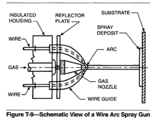
Wire Arc Spray Gun. A schematic view of a wire arc spray gun is shown in Figure T-9. A welding power supply is required to maintain the arc between the two wires.
The arc temperatures exceed the melting point of the spray material. During the melting cycle, the metal is superheated to the point where some volatilization may occur, especially with aluminum and zinc. The high particle temperatures produce metallurgical interactions or diffusion zones, or both, after impact with the substrate. These localized reactions form minute weld spots with good cohesive and adhesive strengths. Thus the coatings develop excellent bond strengths.
Power Source. Direct current constant potential power sources are normally used for wire arc spraying; one wire is positive (anode) and the other is negative (cathode). The tip of the cathode wire is heated to a higher temperature than the tip of the anode wire and melts at a faster rate. Consequently, the particles atomized from the cathode are much smaller than those from the anode wire when the two wires are of the same diameter.
The d-c power source, providing a voltage of 18 to 40 volts, permits operation over a wide range of metals and alloys. The arc gap and spray particle size increase with a rise in voltage. The voltage should be kept at the lowest possible level, consistent with good arc stability, to provide the smoothest coatings and maximum coating density.
Wire Control Unit. The wire control unit consists of two reel (or coil) holders, which are insulated from each other and connected to the spray gun with flexible insulated wire guide tubes. Wire sizes range from 1.6 to 3.2 mm (1/16 to 1/8 in.). Wires of larger diameters are usually in coil form, while smaller diameter wires are preferably level wound on reels or in barrels.
System Operations. Wire arc spray systems can be operated from a control console or from the gun. The control console will have the switches and regulators necessary for controlling and monitoring the operating circuits that power the gun and control the spray procedure, namely the following:
(1) A direct current power source, usually of the constant voltage type
(2) A dual wire feeding system
(3) A compressed gas supply with regulators and flow meters built into the control assembly
(4)Arc spray gun and related console switching
After the first pass has been applied over the entire surface of the workpiece, subsequent spraying is done using the lowest possible arc voltage consistent with good arc stability, and the normal spray gun-to-work distance. These conditions ensure the following:
(1) Fine particle size
(2) Minimum loss of alloy constituents
(3) A concentrated spray pattern
(4)High melting rate
Plasma Arc Spraying
Turbine and rocket engine components are exposed to extreme service conditions. Existing engineering materials will not stand up to these conditions without a protective thermally sprayed coating. In many cases, the spray coating consists of ceramic oxides and carbides which require temperatures higher than those possible with flame and arc processes. The plasma spray process evolved to meet these needs.
The plasma spray process also stimulated the evolution of a new family of materials and application techniques for a greatly expanded range of industrial applications. Plasma spraying supplements the older processes of flame and wire arc spraying.
In the plasma spray process, a gas or gas mixture is passed through an electric arc between a coaxially aligned tungsten alloy cathode and an orifice within a copper anode. The process is illustrated in Figure T-10. The gas passing through the orifice is ionized.
The temperature of the ionized plasma is much higher than that obtained with a combustion flame.
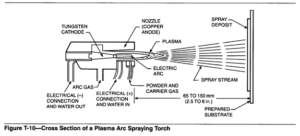
As the plasma jet exits the gun, disassociated molecules of a diatomic gas recombine and liberate heat. The powder is introduced into the plasma, melted, and propelled onto the workpiece by a high-velocity gas stream. The heat content, temperature, and velocity of the plasma jet are controlled by the nozzle type, the arc current, the mixture ratio of gases and the gas flow rate.
The arc operates on direct current from a welding type power supply. The electric power to the arc is governed by a central control unit that regulates the flow of plasma gas and cooling water, and sequences these elements to allow the process to operate reliably and precisely. Either nitrogen or argon is used as the plasma forming gas. A secondary gas, either hydrogen or helium, may be added to increase the heat content and velocity of the plasma.
Controlled Atmosphere Plasma Spraying. Plasma arc spraying lends itself to controlled atmosphere applications. Temperature regulation of both the substrate and atmosphere are more precise in controlled atmospheres. This results in lower oxidation of the sprayed materials and less porosity in the sprayed deposit. It also produces closer control of the composition and morphology of the sprayed coating. This results in greater structural homogeneity, absence of oxide, increased hardness, and a thicker deposit capability.
These benefits are produced at a higher deposition rate.
Fused Spray Deposits
A fused spray deposit is a self-fluxing alloy depos- ited by thermal spraying, which is subsequently heated to coalescence within itself and with the substrate. The materials wet the substrate without the addition of a fluxing agent, provided the substrate is properly cleaned and prepared to receive it. The materials are powdered nickel or cobalt alloys, and they may be applied by powder flame spraying or by plasma spraying.
The application of a fused deposit involves four operations:
(1) Surface preparation
(2) Spraying the self-fluxing alloy
(3) Fusing the coating to the substrate
(4) Finishing the coating to meet surface and dimensional requirements
Fused coatings are dense and nearly porosity free. The alloy compositions can result in hardness levels greater than 50 HRC. Coating thickness is limited to those ranges which can be heated to melting temperature without spalling. Self fluxing coatings are limited to applications where the effects of fusing temperatures and any distortion can be tolerated. Thick coatings of dissimilar metals can be applied in multiple passes. For optimum results, the surface to be coated should be cleaned of all oxide residues after each fusing stage or layer.
A properly sprayed and fused deposit will be nearly homogeneous, metallurgically bonded to the substrate, and have no open or visible porosity. It will have higher hardness than an equivalent mechanically bonded deposit, and will withstand pressures and environments better than non-fused deposits.
Self-Fluxing Alloys. Most self-fluxing alloys fall into two general groups: nickel-chromium-boron-silicon alloys and cobalt-chromium-boron-silicon alloys. In some cases tungsten carbide or chromium carbide particles are blended with an alloy from one of these groups.
The boron and silicon additions are crucial elements that act as fluxing agents and as melting point depressants. They permit fusing at temperatures compatible with steels, certain chromium-iron alloys, and some nickel base alloys.
The hardness of fused coatings will range from 20 to 60 HRC, depending upon alloy composition. Hardness is virtually unaffected by the thermal spraying procedures since there is almost no dilution with the base metal.
In addition to cleaning, blasting, thermal spraying, and work-handling equipment, some device or method is needed to fuse the sprayed deposit. Fusing may be done with an oxyfuel gas torch, in a furnace, or by induction heating.
Thermal sprayed deposits can be fused to a wide variety of substrates. Some base metals are easier to surface than others. Those which can be readily sprayed with one or more self-fluxing alloys and then fused are:
(1) Carbon and low-alloy steel with less than 0.25% carbon
(2) AISI 300 series stainless steels, except Types 303 and 321 ‘
(3) Certain grades of cast iron
(4) Nickel and nickel alloys that are free of titanium and aluminum
Metals that require special procedures to avoid undesirable metallurgical changes are carbon and low alloy steels with more than 0.25% carbon, and AISI 400 series stainless steels, except Types 414 and 431.
Types 414, 431, and the precipitation hardening stainless steels are not recommended as base metals for self-fluxing alloys.
Cracking of some types of fused sprayed deposits on hardenable steels (above 25 HRC) can be avoided by isothermal annealing of the parts from the fusing temperature.
Post-Treatments
Sealing. Sealing of sprayed deposits is performed to lengthen the service life or prevent corrosion of the substrate, or both. Sprayed deposits of aluminum or zinc may be sealed with vinyl coatings, either clear or aluminum pigmented. The sealer may be applied to fill only subsurface pores in the deposit, or both subsurface pores and surface irregularities. The latter technique will provide a smooth coating to resist industrial atmospheres. The vinyl coatings may be applied with a brush or spray gun.
Epoxies, silicones, and other similar materials are used as sealants for certain corrosive conditions. Vacuum impregnations with plastic solutions are also possible.
Diffusing. A thin layer of aluminum may be diffused into a steel or silicon bronze substrate at 760°C (1400°F). The diffused layer can provide corrosion protection against hot gases up to 870°C (1600°F). After depositing the aluminum, the part can be coated with an aluminum pigmented bitumastic sealer or other suitable material, to prevent oxidation of the aluminum during the diffusion heat treatment. There are similar aircraft applications with diffusion temperatures dependent upon the base material to which the aluminum is applied.
Surface Finishing. Techniques for surface finishing of thermal spray deposits differ somewhat from those commonly used for metals. Most sprayed deposits are primarily mechanically bonded to the substrates, except for fused coatings. Excessive pressure or heat generated in the coating during the finishing operation can cause damage such as cracking, crazing, or separation from the substrate.
The selection of a finishing method depends on the type of deposit material, its hardness, the coating thickness, as well as dimensional and surface roughness requirements. Spray deposits of soft metals are usually finished by machining. Hardfaced substrates and ceramic sprayed coatings are usually finished by grinding.
Various other finishing methods are occasionally used. These include buffing, tumbling, burnishing, belt polishing, lapping, and honing.
Properties of Thermal Sprayed Deposits
The quality and the properties of thermal sprayed deposits are largely determined by the size, temperature, and velocity of the spray droplets as they impinge on the substrate, and the degree of oxidation of both the droplets and the substrate during spraying. These factors will vary with the method of spraying and the procedures employed.
The physical and mechanical properties of a spray deposit normally differ greatly from those of the original material. The deposit structure is lamellar and nonhomogeneous, and its cohesion is generally the result of mechanical interlocking. For these reasons, spray deposits should be considered as a separate and distinct form of fabricated material.
Oxide spray deposits tend to retain their physical properties with only modest losses. The chemical compositions of reactive type ceramics, such as carbides, silicides, and borides normally change when the materials are sprayed in air with the flame or plasma methods.
Microstructure. The microstructure of a transverse section through a flame sprayed metal deposit will show a heterogeneous mixture of layered metal particles (white), metal oxide inclusions (gray), and pores (black). A photomicrograph of a transverse section through a flame sprayed deposit of 0.80% carbon steel is shown in Figure T- 11. The light layered particles are bonded to one another by chemical and mechanical interactions.
The microstructure of the polished and etched surface of the 0.80% carbon steel deposit is shown in Figure T-12. It has an emulsified appearance because the flattened steel particles (light) are separated by the oxide (gray).
As-sprayed, self-fluxing alloy deposits are oxidation resistant in nature. As shown in Figure T-13, the microstructure of a fused nickel-chromium self-fluxing alloy deposit has a cast structure with some porosity and inclusions. The roughness of the prepared substrate (bottom of figure) is also evident.
Hardness. The heterogeneous structures of spray deposits generally have a lower macrohardness than the original rod or wire supplied to the gun. However, the hardness of individual deposit particles (micro- hardness) may be much higher than that of the overall deposit. The type of hardness test should be selected to give either the overall deposit hardness or the particle hardness. The thickness of the deposit must also be considered.
The Brinell and Rockwell hardness tests can be used to determine the hardness of fairly thick metallic deposits. Superficial Rockwell and Vickers hardness tests are suitable for thin metallic deposits.
Hardness tests with diamond indenters should be avoided. Microhardness tests can be used to determine the hardness of individual particles. The Knoop inden- tation hardness test is best suited for this.
Bond Strength. The strength of the bond between a spray deposit and the substrate depends upon many factors, including the following:
(1) Substrate material and its geometry
(2) Preparation of the substrate surface
(3) Spray angle to substrate
(4)Preheat
(5) Bond layer material and its application method and procedures
(6) Deposit material and its application method and procedures
(7) Thickness of deposit
(8) Post spraying thermaltreatment
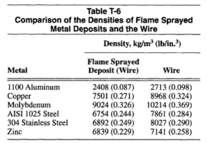
Density. Thermal sprayed deposits have densities less than 100% of the filler metals used because they are porous and contain some oxide. The densities of the flame sprayed deposits and the original wire for several metals are shown in Table T-6.
Coating Selection and Applications
The selection of a proper coating material involves more than choosing the desired properties of the deposit. It should be approached as an engineering problem by considering such items as coating function and service environment, in addition to the physical and chemical properties of both the coating and the substrate. The properties of conventional materials are well understood, and their service performance predictable. This is not true of thermal spray coatings. The mechanical and corrosion resistant properties of sprayed materials differ from solid or powder metal parts of the same chemistry. Coating material selection should be based on properties related to end use and service environment, plus factors involving its compatibility with the substrate. It is not difficult to select the proper coating for a given function after all the pertinent factors are taken into consideration.
Wear Resistance. In the mechanical field, thermal spray hardfacing materials can be used to combat many types of wear. The ability of metal spray deposits to absorb and maintain a film of lubricant is a distinct advantage in many applications.
Electrical Characteristics. The electrical resistance of a metal spray deposit may be 50 to 100% higher than that of the same metal in cast or wrought form. This must be considered in the design of spray deposits for electrical conductors. Such applications include spraying of copper on electrical contacts, carbon brushes, and glass in automotive fuses, as well as silver or copper contacts.
In the field of electrical insulation, various ceramic deposits can be used for insulators. Magnetic shielding of electrical components may be provided with deposits of zinc or tin zinc applied to electronic cases and chassis. Condenser plates can be made by spraying aluminum on both sides of a cloth tape.
Foundry. Changes in contour of expensive patterns and match plates can be readily accomplished by the application of thermal spray deposits followed by appropriate finishing. Patterns and molds can be repaired with wear resistant deposits. Blow holes in castings that appear during machining can be filled to salvage the parts.
Brazing and Soldering. Thermal spraying is frequently used for the preplacement of solder or brazing filler metals. The usual practice is to apply the filler metal using thermal spraying techniques.
Aircraft and Missiles. Thermal spraying is used for air seals and wear-resistant surfaces to prevent fretting and galling at elevated temperatures. Deposits of alumina and zirconia are used for thermal insulation.