A group of welding processes that produces coalescence of the faying surfaces with the heat obtained from resistance of the workpieces to the flow of the welding current in a circuit of which the workpieces are a part, and by the application of pressure.
The theory of resistance welding is based on the principle that a low-voltage, high-amperage current flows through a heavy copper conductor, encountering little resistance until it reaches the material to be welded. Current flow through the greater resistance of the material being welded causes intense heat to be generated, then pressure is applied which forces together the two pieces being welded. The resulting weld between these two pieces is as strong as the weaker of the two pieces that have been joined.
Resistance welding is accomplished by clamping the work (two or more sheets of metal) between copper electrodes and passing an electric current through it. The heat generated at the point of contact between the pieces reduces the metal to a plastic state, and using clamping pressure, induces fusion.
Historical Background
The principle of resistance welding was discovered by the English physicist, James Joule, in 1856. In his experiments he buried a bundle of wire in charcoal and welded the wires by heating them with an electric cur- rent. This is believed to be the first application of heating by internal resistance for welding metal. It remained for Elihu Thompson to perfect the process and develop it for practical applications.
In 1877 Thompson invented a small low-pressure resistance welding machine. Welding was accomplished with this machine by causing the internal resistance in the workpiece to generate the heat required to reach its plastic stage. For several years, little was done with this development, since it seemed to have little commercial value. Nevertheless, resistance welding was introduced commercially in the early 1880s as incandescent welding.
Modern Resistance Welding Technology
Spot, seam, and projection welding are three resistance welding processes in which coalescence of metals is produced at the faying surfaces by the heat generated by the resistance of the work to the passage of electric current. Force is always applied before, during, and after the application of current to confine the weld contact area at the faying surfaces and, in some applications, to forge the weld metal during postheating. Figure R-7 illustrates the three processes.

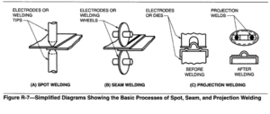
In spot welding, a nugget of weld metal is produced at the electrode site, but two or more nuggets may be made simultaneously using multiple sets of electrodes. Projection welding is similar except that nugget location is determined by a projection or embossment on one faying surface, or by the intersection of parts in the case of wires or rods (cross-wire welding). Two or more projection welds can be made simultaneously with one set of electrodes.
Seam welding is a variation of spot welding in which a series of overlapping nuggets is produced to obtain a continuous, leak tight seam. One or both electrodes are generally wheels that rotate as the work passes between them. A seam weld can be produced with spot welding equipment but the operation will be much slower.
A series of separate spot welds may be made with a seam welding machine and wheel electrodes by suitably adjusting the travel speed and the time between welds. Movement of the work may or may not be stopped during the spot weld cycle. This procedure is known as roll spot welding.
Principles of Operation
Spot, seam, and projection welding operations involve a coordinated application of electric current and mechanical pressure of the proper magnitudes and durations. The welding current must pass from the electrodes through the work. Its continuity is assured by forces applied to the electrodes, or by projections which are shaped to provide the necessary current density and pressure. The sequence of operation must first develop sufficient heat to raise a confined volume of metal to the molten state. This metal is then allowed to cool while under pressure until it has adequate strength to hold the parts together. The current density and pressure must be such that a nugget is formed, but not so high that molten metal is expelled from the weld zone. The duration of weld current must be sufficiently short to prevent excessive heating of the electrode faces. Such heating may bond the electrodes to the work and greatly reduce their life.
The heat required for these resistance welding processes is produced by the resistance of the workpieces to an electric current passing through the material. Because of the short electric current path in the work and limited weld time, relatively high welding currents are required to develop the necessary welding heat.
Heat Generation. In an electrical conductor, the amount of heat generated depends upon three factors:
(1) the amperage,
(2) the resistance of the conductor (including interface resistance), and
(3) the duration of current. These three factors affect the heat generated
as expressed in the formula:
Q = 12Rt
where:
Q = heat generated, joules
I = current, amperes
R = resistance of the work, ohms
t = duration of current, seconds
The heat generated is proportional to the square of the welding current and directly proportional to the resistance and the time. Part of the heat generated is used to make the weld and part is lost to the surrounding metal.
The secondary circuit of a resistance welding machine and the work being welded constitute a series of resistances. The total resistance of the current path affects the current magnitude. The current will be the same in all parts of the circuit regardless of the instantaneous resistance at any location in the circuit, but the heat generated at any location in the circuit will be directly proportional to the resistance at that point.
An important characteristic of resistance welding is the rapidity with which welding heat can be produced. The temperature distribution in the work and electrodes, in the case of spot, seam, and projection welding, is illustrated in Figure R-8. There are, in effect, at least seven resistances connected in series in a weld that account for the temperature distribution. For a two-thickness joint, these are the following:
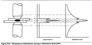
(1) 1 and 7,the electrical resistance of the electrode material.
(2) 2 and 6, the contact resistance between the electrode and the base metal. The magnitude of this resistance depends on the surface condition of the base metal and the electrode, the size and contour of the electrode face, and the electrode force. (Resistance is roughly inversely proportional to the contacting force.) This is a point of high heat generation, but the surface of the base metal does not reach its fusion temperature during the current passage, due to the high thermal conductivity of the electrodes (1 and 7)and the fact that they are usually water cooled.
(3) 3 and 5, the total resistance of the base metal itself, which is directly proportional to its resistivity and thickness, and inversely proportional to the cross-sectional area of the current path.
(4) 4, the base metal interface resistance at the location where the weld is to be formed. This is the point of highest resistance and, therefore, the point of greatest heat generation. Since heat is also generated at points 2 and 6, the heat generated at interface 4 is not readily lost to the electrodes. Heat will be generated in each of the seven locations in Figure R-8 in proportion to the resistance of each. Welding heat, however, is required only at the base metal interface, and the heat generated at all other locations should be minimized. Since the greatest resistance is located at 4,heat is most rapidly developed at that location. Points of next lower resistance are 2 and 6. The temperature rises rapidly at these points also, but not as fast as at 4. After about 20% of the weld time, the heat gradient may conform to the profile shown in Figure R-8. Heat generated at 2 and 6 is rapidly dissipated into the adjacent water-cooled electrodes 1 and 7. The heat at 4 is dissipated much more slowly into the base metal. Therefore, while the welding current continues, the rate of temperature rise at plane 4 will be much more rapid than at 2 and 6. The welding temperature is indicated on the chart at the right of Figure R-8 by the number of dots within the drawing leading to the matching curve.
Factors that affect the amount of heat generated in the weld joint by a given current for a unit of weld time are (1) the electrical resistances within the metal being welded and the electrodes, (2) the contact resistances between the workpieces and between the electrodes and the workpieces, and (3) the heat lost to the workpieces and the electrodes.
A comprehensive and detailed description of resistance welding principles of operation, individual processes, power sources, machines, electrodes, key welding parameters, weld schedules, welding methods, and weldability of major metals and alloys can be found in the American Welding Society Welding Handbook, 8th Edition, Volumes 2, 1991; and Welding Handbook Volume 3, 1996, Miami, Florida.

Variations in the composition, shape and thickness of materials require different techniques to maintain productivity. For example, if one of the pieces to be resistance spot welded is considerably thicker than the other, the thin piece would heat much quicker and melt before the thick piece reached welding temperature. One solution to this problem is to fashion a projection (see Figure R-7) on the thicker sheet at the place to be welded. This projection concentrates the heat in a small area on the thicker sheet and brings it up to melting temperature at the same time as the thinner sheet.
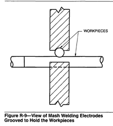
Mash Welding- Mash welding is the term used to describe the spot welding of two wires or rods at an angle to one another. See Figure R-9, which shows how the electrodes are grooved to hold the stock. This method, also called cross wire welding, is used to weld such items as wire wastebaskets and lampshade frames.