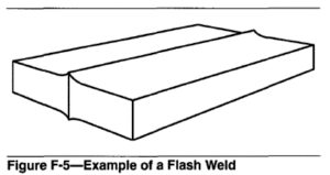
A resistance welding process that produces a weld at the faying surfaces of a butt joint by a flashing action and by the application of pressure after heating is substantially completed. The flashing action, caused by the very high current densities at small contact points between the workpieces, forcibly expels the material from the joint as the workpieces are slowly moved togethel: The weld is completed by a rapid upsetting of the workpieces. See Figure F-5.
Two parts to be joined are clamped in dies (electrodes) connected to the secondary of a resistance welding transformer. Voltage is applied as one part is advanced slowly toward the other. When contact occurs at surface irregularities, resistance heating occurs at these locations. High amperage causes rapid melting and vaporization of the metal at the points of contact, and then minute arcs form. This action is called “flashing.” As the parts are moved together at a suitable rate, flashing continues until the faying surfaces are covered with molten metal and a short length of each part reaches forging temperature. A weld is then created by the application of an upset force to bring the molten faying surfaces in full contact and forge the parts together. Flashing voltage is terminated at the start of upset. The solidified metal expelled from the interface is called “flash.”
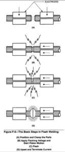
The basic steps in a flash welding sequence are as follows:
(1) Position the parts in the machine.
(2) Clamp the parts in the dies (electrodes).
(3) Apply the flashing voltage.
(4)Start platen motion to cause flashing.
(5) Flash at normal voltage.
(6) Terminate flashing.
(7) Upset the weld zone.
(8) Unclamp the weldrnent.
(9) Return the platen and unload.
Figure F-6 illustrates these basic steps. Additional steps such as preheat, dual voltage flashing, postheat, and trimming of the flash may be added as the application dictates.
Flashing takes place between the faying surfaces as the movable part is advanced toward the stationary part. Heat is generated at the joint and the temperature of the parts increases with time. Flashing action (metal loss) increases with part temperature.
A graph relating part motion with time is known as the flashing pattern. In most cases, a flashing pattern should show an initial period of constant velocity motion of one part toward the other to facilitate the start of flashing. This linear motion should then merge into an accelerating motion which should closely approximate a parabolic curve. This pattern of motion is known as “parabolic flashing.”
Upset occurs when a stable temperature distribution is achieved by flashing and the two parts are brought together rapidly. The movable part should be accelerated rapidly so that the molten metal on the flashing surfaces will be extruded before it can solidify in the joint. Motion should continue with sufficient force to upset the metal and weld the two pieces together.
Upset current is sometimes applied as the joint is being upset to maintain temperature by resistance heating. This permits upset of the joint with lower force than would be required without it. Upset current is normally adjusted by electronic heat control on the basis of either experience or welding tests.
Advantages and Limitations
Butt joints between parts with similar cross section can be made by friction welding and upset welding, as well as by flash welding. Listed below are some important advantages of flash welding:
(1) Cross sectioned shapes other than circular can be flash welded: for example, angles, H sections, and rectangles. Rotation of parts is not required.
(2) Parts of similar cross section can be welded with their axes aligned or at an angle to each other, within limits.
(3) The molten metal film on the faying surfaces and its ejection during upset acts to remove impurities from the interface.
(4)Preparation of the faying surfaces is not critical except for large parts that may require a bevel to initiate flashing.
(5) Rings of various cross sections can be welded.
(6) The heat-affected zones of flash welds are much narrower than those of upset welds.
The following are some limitations of the process:
(1) The high single-phase power demand produces unbalance on three-phase primary power lines.
(2) The molten metal particles ejected during flashing present a fire hazard, may injure the operator, and may damage shafts and bearings. The operator should wear face and eye protection, and a barrier or shield should be used to block flying sparks.
(3) Removal of flash and upset metal is generally necessary and may require special equipment.
(4)Alignment of workpieces with small cross sections is sometimes difficult.
(5) The parts to be joined must have almost identical cross sections.
Applications
Base Metals. Many ferrous and nonferrous alloys can be flash welded. Typical metals are carbon and low alloy steels, stainless steels, aluminum alloys, nickel alloys. and copper alloys. Titanium alloys can be flash welded, but an inert gas shield to displace air from around the joint is necessary to minimize embrittlement.
Dissimilar metals may be flash welded if their upsetting characteristics are similar. Some dissimilarity can be overcome with a difference in the initial extensions between the clamping dies, adjustment of flashing distance, and selection of welding variables. Typical examples are welding of aluminum to copper or a nickel alloy to steel.
Typical Products. The automotive industry uses wheel rims produced from flash welded rings that are formed from flat cold-rolled steel stock. The electrical industry uses motor and generator frames produced by flash welding plate and bar stock previously rolled into cylindrical form. Cylindrical transformer cases, circular flanges, and seals for power transformer cases are other examples. The aerospace industry uses flash welds in the manufacture of landing gear struts, control assemblies, hollow propeller blades, and rings for jet engines and rocket casings.
The petroleum industry uses oil drilling pipe with fittings attached by flash welding. Several major railroads are using flash welding to join relatively high carbon steel track. In many cases, welding is done in the field using welding machines and portable generating equipment mounted on railroad cars.
Miter joints are sometimes used in the production of rectangular frames for windows, doors, and other architectural trim. These products are commonly madeof plain carbon and stainless steels, aluminum alloys, brasses, and bronzes. Usually the service loads are
limited, but appearance requirements of the finished joints are stringent.
Equipment
Typical Machines. A typical flash welding machine consists of six major parts:
(1) The machine bed which has platen ways attached
(2) The platens which are mounted on the ways
(3) Two clamping assemblies, one of which is rigidly attached to each platen to align and hold the parts to be welded
(4) A means for controlling the motion of the movable platen
(5)A welding transformer with adjustable taps
(6) Sequencing controls to initiate part motion and flashing current
Flash welding machines may be manual, semi-automatic, or fully automatic in their operations; however, most of them are either semi-automatic or fully automatic.
Controls and Auxiliary Equipment. Electrical controls on flash welding machines are integral types designed to sequence the machine, control the welding current, and precisely control the platen position during flashing and upsetting.
Dies. Flash welding dies, compared to spot and seam welding electrodes, are not in direct contact with the welding area. Dies may be considered work holding and current-conducting clamps. The dies are usually mechanically fastened to the welding machine platens.
Fixtures and Backups
The functions of fixtures for flash welding are (1) to rapidly and accurately locate two or more parts relative to each other, (2) to hold them in proper location while they are being welded, and (3) to permit easy release of the welded assembly. A fixture is either fastened to the machine or built into it. Parts are loaded directly into the fixture and welded.
Joint Design
In general, the two parts to be welded should have the same cross section at the joint. Bosses may have to be machined, forged, or extruded on parts to meet this requirement. In the flash welding of extruded or rolled shapes with different thicknesses within the cross-section, the temperature distribution during flashing will vary with section thickness. This tendency can often be counteracted by proper design of the clamping dies, provided the ratio of the thicknesses does not exceed about 4 to 1.
Welding Procedures
Every welding operation involves numerous variables that affect the quality of the resulting weld. For this reason, a welding procedure should be developed that prescribes the settings for the welding variables to ensure consistent weld quality. Flash welding involves dimensional, electrical, force, and time variables. These and other considerations in flash welding, such as surface preparation, heat balance, initial die opening, flash removal, process variables, weld quality, testing and inspection, and recommended reading list are covered in the following reference: American Welding Society. Welding Handbook, 8th Edition, Vol. 2, Miami, Florida: American Welding Society, 1991.
Safety. Operating personnel should be given instructions on how to operate the machinery in a safe manner. Hands must be kept clear of moving machinery, and contact with electrically charged surfaces must be avoided. The area around the machine must be kept free of combustibles that might be ignited by molten flash. Additional nformation on safe practices for welding may be found in American National Standard 249.1, Safety in Welding and Cutting, latest edition.