Most welds in cast irons are made with an arc welding process such as shielded metal arc welding (SMAW), flux cored arc welding (FCAW), gas metal arc welding (GMAW), gas tungsten arc welding (GTAW), and submerged arc welding (SAW). The
high energy concentration associated with these processes allows highly localized fusion of both the cast irons and the electrodes. But this results in high cooling rates and localized thermal expansion, neither of which is desirable. Even so, reliable, high-quality
welds can be produced when proper procedures and suitable filler metals are used. Prior to the development of the SMAW processes, the carbon arc welding (CAW) process was used extensively for welding cast irons. Few, if any, shops still consider CAW as a viable
technique.
Welding Considerations
Because of the considerable differences in the composition and microstructure of the cast irons, it is essential to identify the type of cast iron before welding begins. Some insight about the type of iron can be determined from the appearance of fractures, an examination of the microstructure, or from hardness measurements. A chemical analysis would also be helpful. When no information is obtainable, the iron could be assumed to be gray cast iron because of its general use, and the procedures selected on that basis.
The selection of the filler metal, the energy input, and the preheat are very important to successful welding. Selection of the welding process is also important
in establishing the procedures and materials to be used.
When welding cast iron with a steel electrode, there are four important zones in the vicinity of the weld: the weld metal area, the alloyed weld metal zone, the heat affected zone, and the original cast iron. See Figure C-1. In C-1, Section A is deposited steel, unaffected by dilution. Section B is also steel deposited from the electrode, but changed from a soft steel to a rather high-carbon steel. This is due to alloying with carbon from the cast iron.
Cast iron which was brought up to melting temperature, then chilled by the cold mass of the casting, is shown as Section C, the heat-affected zone. The result is a metal which is extremely hard and brittle. This hardening is due to rapid cooling, which prevents the iron carbide from changing into iron and graphite. The metal in this area is white iron; the controlling component is cementite.
Section D is the original cast iron.
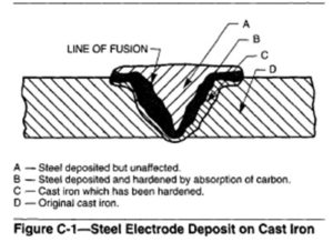
Failure of a welded joint of the type shown in Figure C-1 will usually occur in the cast iron adjacent to the line of fusion, because the hardened cast iron is more brittle than the high-carbon steel on the steel side of the line of fusion.
A specific reference is ANSI/AWS D11.2, Guide for Welding Iron Castings, published by the American Welding Society.
Preheating to slow the rate at which the welds cool is important to the success of welding cast irons. It is not a question of whether to use preheat or not, but what the temperature should be, and how it should be distributed. Preheat prevents cracks caused by thermal stresses, reduces residual stresses, distortion, and hardness in the HAZ. It burns off undesirable organic contaminants such as oils and greases. As a general rule,
to prevent cracking, the minimum preheat temperature should be about 40°C (100°F) for malleable irons; between 150 and 260°C (300 and 500’F) for gray irons, depending on the alloy content; between 200 and 315°C (400 and 600°F) for ductile irons, depending on the alloy content, and above 315°C (600°F) for white irons to prevent the formation of martensite. The filler metal is an important consideration in preheating, with lower temperatures being acceptable with weaker welds. The temperature selected and the distribution of heat within a casting are also dependent on the complexity of the shape and size of the casting, (with the more complex shapes and larger sizes requiring more heat), and the need to produce compressive stresses in the vicinity of the weld joint. Slow cooling of the casting after welding is also necessary. Very slow cooling can be accomplished by burying the casting in sand or other material or, at the very least, covering it with a heat resistant fabric to minimize radiation and convective cooling.
Thermal Stresses
When a section of metal is heated or cooled, the expansion or contraction which takes place will produce stresses. This can be visualized by comparing this effect to that produced by driving a wedge between the sections at the point of heat application.
The greatest stress is exerted at a time when the metal is just below the point of fusion, or at the time contraction has taken place. The effect of these stresses is illustrated in Figure C-2. Assume that Item 1 is to be welded at the point marked “W” and that the casting
section at the point of welding is 13 by 2.5 cm (5 by 1in.). An application of welding heat at the point “W’ continues to expand the metal at this point until a point just below the fusion is reached. This expansion causes the free end to move outward in order to accommodate the greater bulk of material at the weld, just as if a wedge were being driven into the metal. After the metal solidifies, this greater bulk begins to recede or contract and continues to do so until a point is reached at which the casting has cooled to ambient temperature. With this contraction there is a corresponding movement of the free end of the casting. If, instead of the casting having the flat section shown in Item 1, it takes the form of that shown in Item 2, where the leg section is similar to three sides of a square, the leg, instead of being free to move, is held more rigidly, causing considerable strain on the lower side of the section and opposite the weld.
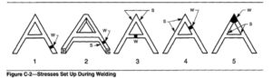
Contraction Strains– On cooling, contraction takes place as in the previous example, causing a severe strain in the lower section. If the casting is solid and the section so heavy that the welding heat does not penetrate all the way through, there is the same expansion and contraction with the accompanying stresses and strains which often result in warpage and breakage. Items 3,4 and 5 in Figure C-2 show similar examples; the points “W’ representing the places of welding and the points “S” where the greatest strain is exerted. Breakage from expansion and contraction stresses does not always occur at the point of greatest stress application, but at a point where the strength of the section is less than that required to withstand the stress applied at that point. An example of this is shown in Item 3, where the weld is made in the cross member between the legs, and the strain is distributed about the apex of the angle formed at the junction of the legs. If the section of the apex is heavy enough to withstand the energy exerted, the breakage, if any, would then take place in the leg sections and at a point which is less able to withstand the applied stress at that particular point. A close study of the construction of each particular casting is necessary so that proper precautions and care can be exercised when designing the joint, preparing it for welding, and completing the weld.
Special Techniques
The reliability of welds in cast irons can be improved with several techniques. One involves a mechanical method called studding, in which studs are positioned as needed in the weld joint to reinforce the welded joint. (See CAST IRON STUDDING and ARC STUD WELDING).
Another technique involves weld face grooving, in which staggered grooves are cut along the faces of joints to accept stringer welds. They prevent potential cracks from propagating in completed welds.
Peening can be very helpful in reducing residual tensile stresses. It is most effective when used on welds which are at red heat, but not below 540°C (1000°F). Peening can be accomplished by hand with a ball peen hammer or with an air hammer.
Preventing Cracks- Cracking can also be reduced by depositing the welds in a specific sequence and direction. In welding castings with irregular sections, the area of least strain (the heavy sections) should be welded first, and the area of the greatest strain (the light sections) should be welded last. When welding areas of the various sections, the direction of the weld should be from the heavy section toward the light section, and always toward a comer or edge when possible.
Sound, clean cast iron is an essential requirement for joints to be repaired by welding. Sometimes the weld zone is impregnated with sand and other contaminants which accumulated while the cast component was in use. All foreign materials must be removed, including casting skins, sand, rust, paint, or oil. All of the defective metal must be removed before the welds are made. Sufficient metal must be removed to provide the welder with a large enough opening to achieve full penetration in the root and side walls. The presence of contaminants might not be detected until after some weld metal has been deposited. If such a condition is found, that metal as well as more of the casting must be removed so that sound weld metal can be deposited.
Cracks are often pinned by drilling holes at the ends of the cracks. This reduces the high stress concentrations at the cracks and keeps them from propagating while preparing the joint for welding and while welding. Air carbon arc is the most common process used for removing defects and opening the joints. Following this, the heat-affected zone (HAZ) should be
removed by grinding.
The type of weld groove to be prepared depends on many factors, such as accessibility, anticipated application, the type of cast iron, thickness, the welding process and the filler metal. For example, when using high-nickel fillers, adjustments need to be made for the “sluggishness” of this material, meaning a wider root opening and larger groove angle.
Shielded Metal Arc Welding
Shielded metal arc welding (SMAW) is probably the most widely used process for arc welding cast irons because of its versatility, because it offers the greatest selection of filler metal compositions, and because it can be used in all positions. The SMAW process also has a number of other advantages, such as reasonable deposition rates, low distortion and a narrow heat-affected zone.
Filler Metals for SMAW
Gray Iron Rods. These rods can match the compositions of the castings to be welded, including those with high carbon levels. They are used in the flat position at high currents to produce large fluid puddles. To avoid hot cracking, the arc current should not be interrupted
quickly, but should be decreased slowly to fill the crater and allow it to solidify without cracking. Gray iron rods produce welds which can match the color of the casting as well as its mechanical properties.
Mild Steel Electrodes- Mild steel electrodes such as E7018 are used to repair defects in castings when color match is important, but easy machining is not. To keep the weld hardness down, it is important to minimize dilution and discourage procedures which cause high cooling rates. Another problem is associated with the large shrinkage differences with mild steel and cast
iron: the resultant stresses can be severe enough to cause cracking in the HAZ. To avoid them, preheat is essential.
Nickel Alloy Electrodes- Nickel-alloy electrodes have a special place in the fabrication of cast irons. Nickel offers a number of advantages. First, it has a very low solubility for carbon, so carbon dissolved in the weld metal as the result of dilution is rejected as graphite during solidification. This minimizes shrinkage in the weld metal which, in turn, reduces residual
stresses in the weld joint. Additionally, the nickel-rich alloys are soft, easy to machine and offer high resistance to hot cracking when restrained.
There are four basic categories of nickel-base electrodes:
(1) High-nickel-containing about 85% nickel and alloyed with carbon, silicon, manganese and copper. They are used in applications where the diluted weld metal must be machined.
(2) Nickel-iron-a 50/50 mix of nickel and iron containing the same alloy additions as the high nickel electrodes. The welds are stronger and more ductile, making them more useful for welding ductile or high strength gray irons. They are effective for joining cast irons to dissimilar alloys, such as carbon steel or nickel base alloys. Stainless steels should be buttered with a high-nickel electrode first to keep chromium carbide from forming in the final weld. This alloy has the lowest coefficient of thermal expansion, making it more useful for welding heavy sections.
(3) Nickel-manganese-iron-a 40/40 mix of nickel and iron, containing about 12% manganese. This alloy has the good combination of strength, ductility and cracking resistance. It is used for welding the nodular irons, and in surfacing applications where wear resistance is important.
(4)Nickel-copper-a 60/40 nickel copper alloyed with a little silicon and manganese. These electrodes are used only in applications where dilution can be kept very low, because the addition of iron can cause weld cracking.
Copper Alloy Electrodes- Copper alloy electrodes are used for braze welding cast irons. (See BRAZE WELDING). The most commonly used of these are strengthened with either tin or aluminum. The copper alloy electrode containing aluminum is considerably stronger, but both offer the advantages of being very soft and ductile when hot. This allows it to yield while cooling, relieving stresses that could cause cracking. The strength increases rapidly as the alloys cool to
ambient temperature.
Technique for Deep Welds
When the weld is deep enough to require that several layers be deposited, a special technique is used. This technique utilizes a coated electrode in combination with a filler rod of silicon bronze. The first layer is always made with the electrode alone; the silicon bronze is not added until subsequent layers. The operator uses one hand to maintain the arc with the electrode
and feeds the bronze wire into the pool with the other hand. The filler rod is held close to the arc and is added by intermittently bringing its end into contact with the pool behind the electrode. Care has to exercised so that the feed rod will not make contact with the electrode. See CAST IRON; CAST IRON, Oxyacetylene Welding, and CAST IRON, Malleable.
The GMAW process is most commonly used with the spray-arc mode of metal transfer, a high-energy technique. Producing a large heat-affected zone (HAZ) and deep penetration, it is more likely to cause weld or HAZ cracking. The buried-arc mode, which is sometimes used for welding carbon steels with C02-rich gases, also produces a deeply penetrating weld. In the
globular mode, however, using argon-rich gases and currents below that at which spray occurs, the weld penetration is very low. Unfortunately, this mode cannot be used in any position except the flat or, possibly, for horizontal fillet welds. The short-circuiting mode allows low penetration welds to be made in all positions; seemingly an ideal combination for welding cast irons. However, due to the very low energy associated with this mode, lack-of-fusion defects must be
expected when welding thicknesses greater than 6 mm (1/4 inch).
Filler Metals- The variety of electrodes available for GMAW is not as extensive as those available for SMAW. This is because small diameter wires are required for the gas shielded processes, meaning that the alloys must have reasonably good ductility in order to be drawn. For this reason, high-carbon, nickel-rich wires cannot be made economically. It is possible to use the same alloys designed for welding steels. They provide an excellent color match; however, they must be used with care, and because dilution causes the welds to be very hard, they cannot be machined. Preheat is essential.
When dilution must be tolerated and the welds must be machined, alloys containing 95% or more nickel are required. Nickel-iron wires are also available, but they deposit hard welds which are crack sensitive. The same nickel-manganese-iron alloy used for SMAW offers the same high strength and crack resistance for GMAW welding. Copper-tin and copper-aluminum
wires can also be used and, with globular or short-circuiting transfer, these wires can be used for braze welding. See BRAZE WELDING.
Flux-Cored Arc Welding
Like the solid wires used for the GMAW process, the cored wires used with this modification of GMAW must be ductile. However, since alloys can be incorporated in the core, many compositions can be produced without causing either drawing or feeding difficulties. In addition, some of the cored wires can incorporate constituents which provide protection to the arc and weld pool, eliminating the need for shielding gases. These are the self-shielded cored wires, some of which offer the advantages of high deposition rates and low penetration at relatively low welding currents. They can be used to great advantage for welding heavy sections of cast irons. Some also have basic slags which increase the tolerance for sulfur, thereby reducing the possibility of hot cracking.
Filler Metals- Wires containing 70/30 nickel-iron compositions are available for welding heavy castings. Although these wires are effective for welding thick sections, the welds produced are generally too hard to be machined. Nickel-iron-manganese electrodes with a 60/40 ratio of Ni/Fe deposit stronger and more ductile welds which are machinable. They also can be used to weld cast irons to dissimilar metals.