A group of welding processes that produce coalescence of materials by heating them to the brazing temperature in the presence of a filler metal having a liquidus above 450°C (84OOF) and below the solidus of the base metal. The filler metal is distributed between the closelyfitted faying sufaces of the joint by capillary action. See STANDARD WELDING TERMS.
Brazing must meet each of three criteria:
(1) The parts must be joined without melting the base metals.
(2) The filler metal must have a liquidus temperature above 450°C (840°F).
(3) The filler metal must wet the base metal surfaces and be drawn into or held in the joint by capillary action.
To achieve a good joint using any of the various brazing processes described in this chapter, the parts must be properly cleaned and must be protected by either flux or atmosphere during the heating process to prevent excessive oxidation. The parts must be designed to afford a capillary for the filler metal when properly aligned, and a heating process must be selected that will provide the proper brazing temperature and heat distribution.
Brazing differs from soldering, in that soldering filler metals have a liquidus below 450°C (840°F).
Braze welding is also different from brazing, since the filler metal is not distributed by capillary action.
Brazing with silver alloy filler metals is sometimes called silver soldering, a nonpreferred term. Silver brazing filler metals are not solders; they have liquidus temperatures above 450°C (840°F).
Applications
The brazing process is used to join together various materials for numerous reasons. By using the proper joint design, the resulting braze can function better than the base metals being joined. In many instances it is desirable to join different materials to obtain the maximum benefit of both materials and have the most cost- or weight-effective joint. Applications of brazing cover the entire manufacturing arena from inexpensive toys to highest quality aircraft engines and aerospace vehicles. Brazing is used because it can produce results which are not always available with other joining processes. Brazing provides the following advantages:
(1) It is economical for complex assemblies.
(2) It is a simple way to join large joint areas.
(3) It provides excellent stress and heat distribution.
(4) Coatings and claddings can be maintained during brazing.
(5) Dissimilar materials can be joined.
(6) Nonmetals can be joined to metals.
(7) Widely different thicknesses can be joined.
(8) Complex arrangements of precision parts can be joined.
(9) Joints require little or no finishing.
(10) Many parts can be joined at one time (batch processing).
Process Advantages and Disadvantages
Among the advantages of brazing is that it is generally very economical when done in large batches, with costs varying with the heating method employed. A major benefit of brazing is that brazed joints can be taken apart at a later time. Dissimilar metals can be joined by brazing without melting the base metals as required by other joining methods. In many instances, several hundred parts with multiple joints can be brazed at one time. When protective atmosphere brazing is used, parts are kept clean and a heat treatment cycle may be employed as part of the brazing cycle.
There are some disadvantageous factors of brazing that should be considered. In the brazing process, a molten metal flows between the materials to be joined; consequently there is the possibility of liquid metal interactions which are unfavorable. Depending on the material combinations involved and the thickness of the base sheets, base metal erosion may occur. In many cases, the erosion may be of little consequence, but when brazing heavily loaded or thin materials, the erosion can weaken the joint and make it unsatisfactory for its intended application.
Also, the formation of brittle intermetallics or other phases can make the resulting joint too brittle to be acceptable. A disadvantage of some of the manual brazing processes is that highly skilled technicians are required to perform the operation. This is especially true for gas torch brazing when using a brazing filler metal with a high melting point. Nevertheless, with the proper joint design, brazing filler metal, and process selection, a satisfactory brazing technique can be developed for most joining applications. Brazing is often selected when it is not feasible, because of strength or economic considerations, to join the materials with a fusion welding process.
Principles of Operation
Capillary flow is the dominant physical principle that assures good brazements when both faying surfaces to be joined are wet by the molten filler metal. The joint must be spaced to permit efficient capillary action that results in coalescence. Specifically, capillary action is a result of surface tension between base metal(s) and filler metal, protected by a flux or atmosphere, and promoted by the contact angle between base metal and filler metal. In actual practice, brazing filler metal flow is influenced by dynamic considerations involving fluidity, viscosity, vapor pressure, gravity, and especially the effects of metallurgical reactions between filler metal and base metal.
Brazing Procedure- The typical brazed joint has a relatively large area and very small gap. In the simplest brazing application, the surfaces to be joined are cleaned to remove contaminants and oxides. Next, they are coated with flux. A flux is a material which is capable of dissolving solid metal oxides and also preventing new oxidation. The joint area is then heated until the flux melts and cleans the base metals, which are protected against further oxidation by the layer of liquid flux.
Brazing filler metal is then melted at some point on the surface of the joint area. Capillary attraction between the base metal and the filler metal is much higher than that between the base metal and the flux. Accordingly, the flux is displaced by the filler metal. The joint, on cooling to room temperature, will be filled with solid filler metal, and the solid flux will be found on the joint periphery.
Joints to be brazed are usually made with clearances of 0.025 to 0.25 mm (0.001 to 0.010 in.). The fluidity of the filler metal, therefore, is an important factor. High fluidity is a desirable characteristic of brazing filler metal since capillary action may be insufficient to draw a viscous filler metal into closely fitted joints.
Brazing is sometimes done under an active gas, such as hydrogen, or in an inert gas or vacuum. Atmosphere brazing eliminates the necessity for postbraze cleaning and ensures the absence of corrosive mineral flux residue. Carbon steels, stainless steels, and superalloy components are widely processed in atmospheres of reacted gases, dry hydrogen, dissociated
ammonia, argon, or vacuum. Large vacuum furnaces are used to braze zirconium, titanium, stainless steels, and the refractory metals. With good processing procedures, aluminum alloys can also be vacuum-furnace brazed with excellent results.
Brazing is economically attractive for the production of high strength metallurgical bonds while preserving desired base metal properties.
Brazing Processes
Brazing processes are customarily designated according to the sources or methods of heating. Industrial methods currently significant are the following:
(1) Torch brazing
(2) Furnace brazing
(3) Induction brazing
(4) Resistance brazing
(5) Dip brazing
(6) Infrared brazing
Whatever the process used, the filler metal has a melting point above 450°C (840″F), but below that of the base metal, and it spreads within the joint by capillary action.
Torch Brazing
Torch brazing is accomplished by heating with one or more gas torches. Depending on the temperature and the amount of heat required, the fuel gas Le., acetylene, propane, or natural gas, may be burned with air, compressed air, or oxygen. Flame temperature increases as the oxygen content of the gas is increased.
For manual torch brazing, the torch may be equipped with a single tip, either single- or multiple flame. Manual torch brazing is particularly useful on assemblies involving sections of unequal mass. Machine operations can be set up, where the rate of production warrants, using one or more torches equipped with single or multiple-flame tips. The machine may be designed to move either the work or the torches, or both.
Torch heating for brazing can be used with filler metals supplied with flux or self-fluxing. The list includes aluminum-silicon, silver, copper-phosphorus, copper-zinc, and nickel. With the exception of the copper- phosphorus filler metals, they all require fluxes. For certain applications even the self-fluxing copper phosphorus filler metals require added flux.
The filler metal can be placed on the joint and fluxed before heating, or it may be face-fed. Heat is applied to the joint, first melting the flux, then continuing until the brazing filler metal melts and flows into the joint. Overheating of the base metal and brazing filler metal should be avoided because rapid diffusion and “drop through” of the metal may result. Natural gas is well suited for torch brazing because its relatively low flame temperature reduces the danger of overheating.
Brazing filler metal may be preplaced at the joint in the forms of rings, washers, strips, slugs, or powder, or it may be fed from hand-held filler metal, usually in the form of wire or rod. In any case, proper cleaning and fluxing are essential.
Torch brazing techniques differ from those used for oxyfuel gas welding. Operators experienced only in welding techniques may require instruction in brazing techniques. It is good practice, for example, to prevent the inner cone of the flame from coming in contact with the joint except during preheating, since melting of the base metal and dilution with the filler metal may
increase its liquidus temperature and make the flow more sluggish. In addition, the flux may be overheated and thus lose its ability to promote capillary flow, and low melting constituents of the filler metal may evaporate.
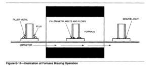
Furnace Brazing
Furnace brazing, as illustrated in Figure B-11, is used extensively. This process is selected in applications where multiple brazed joints are to be formed simultaneously on a completed assembly, and when many similar assemblies are to be joined. It is successful when the following conditions can be met:
(1) the parts to be brazed can be preassembled or jigged to hold them in the correct position,
(2) the brazing filler metal can be placed in contact with the joint, and
(3)the complex parts can be heated uniformly to prevent the distortion that would result from local heating of the joint area.
Electric, gas, or oil heated furnaces with automatic temperature control capable of holding the temperature within k6″C (_+10″Fs) hould be used for furnace brazing. Fluxes or specially controlled atmospheres that perform fluxing functions must be provided.
Parts to be brazed should be assembled with the filler metal and flux, if used, located in or around the joints. The preplaced filler metal may be in the form of wire, foil, filings, slugs, powder, paste, or tape. The assembly is heated in the furnace until the parts reach brazing temperature and brazing takes place. The assembly is then removed. These steps are shown in Figure B- 11.
Many commercial fluxes are available for both genera1 and specific brazing operations. Satisfactory results are obtained if dry powdered flux is sprinkled along the joint. Flux paste is satisfactory in most cases, but in some cases it retards the flow of brazing alloy. Flux pastes containing water can be dried by beating the assembly at 175 to 200°C (350 to 400°F) for 5 to 15 minutes in drying ovens or circulating air furnaces.
To avoid excessive interaction between the filler metal and base metal, brazing time should be restricted to the time necessary for the filler metal to flow through the joint. Normally, one or two minutes at the brazing temperature is sufficient to make the braze. A longer time at the brazing temperature will be beneficial where the remelt temperature of the filler metal is to be increased and where diffusion will improve joint ductility and strength. Times of 30 to 60 minutes at the brazing temperature are often used to increase the braze remelt temperature.
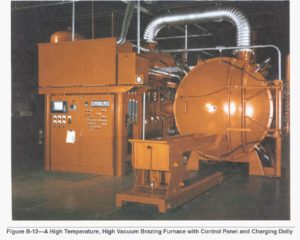
Furnaces- Furnaces used for brazing are classified as (1) batch type with either air or controlled atmosphere, (2) continuous type with either air or controlled atmosphere, (3) retort type with controlled atmosphere, or (4) vacuum. Figure B-12 shows a high-temperature, high-vacuum brazing furnace with control panel and charging carriage.
Most brazing furnaces have a temperature control of the potentiometer type connected to thermocouples and gas control valves or contactors. Most furnaces are heated by electrical resistance using silicon-carbide, nickel-chromium, or refractory metal (Mo, Ta, W) heating elements. When a gas or oil flame is used for heating, the flame must not impinge directly on the parts.
With controlled atmosphere furnaces, a continuous flow of the atmosphere gas is maintained in the work zone to avoid contamination from outgassing of the metal parts and dissociation of oxides. If the controlled atmosphere is flammable or toxic, adequate venting of the work area and protection against explosion are necessary.
Batch type furnaces heat each workload separately. When a furnace is lowered over the work, it is called a bell furnace.
Continuous furnaces are equipped with conveyors so that the furnace receives a steady flow of incoming assemblies. The parts move through the furnace either singly or in trays or baskets. Continuous furnaces usually contain a preheat or purging area which the parts enter first. In this area, the parts are slowly brought to a temperature below the brazing temperature. If brazing atmosphere gas is used in the brazing zone, it also flows over and around the parts in the preheat zone, under positive pressure. The gas flow removes any entrapped air and starts the reduction of surface oxides. Atmosphere gas trails the parts into the cooling zone.
Retort furnaces are batch furnaces in which the assemblies are placed in a sealed retort for brazing. The air in the retort is purged by controlled atmosphere gas and the retort is placed in the furnace. After the parts have been brazed, the retort is removed from the furnace, cooled, and its controlled atmosphere is purged. The retort is opened, and the brazed assemblies are removed. A protective atmosphere is sometimes used within a high-temperature furnace to reduce external scaling of the retort.
Vacuum furnace brazing is widely used in the aerospace and nuclear fields, where reactive metals are joined or where entrapped fluxes would be intolerable. Stainless steels, superalloys, aluminum alloys, titanium alloys, and metals containing refractory or reactive elements are brazed with vacuum brazing equipment. Base metals that can generally be brazed
only in vacuum are those containing more than a few percent of aluminum, titanium, zirconium, or other elements with particularly stable oxides. Vacuum is a relatively economical “atmosphere” which prevents oxidation by removing air from around the assembly.
Surface cleanliness is nevertheless required for good wetting and flow.
Induction Brazing
Induction brazing is used when very rapid heating is required. Time for processing is usually in the range of seconds when large numbers of parts are handled automatically. Induction brazing has been used extensively to produce consumer and industrial products; structural assemblies; electrical and electronic products; mining, machine, and hand tools; military and ordnance equipment; and aerospace assemblies.
The heat for brazing with this process is obtained from an electric current induced in the parts to be brazed, hence the name induction brazing. For induction brazing, the parts are placed in or near a watercooled coil carrying alternating current. They do not form a part of the electrical circuit. Parts to be heated act as the short circuited secondary of a transformer where the work coil, which is connected to the power source, is the primary. On both magnetic and nonmagnetic
parts, heating is obtained from the resistance of the parts to currents induced in them by the transformer action.
The brazing filler metal is preplaced. Careful design of the joint and the coil setup are necessary to assure that the surfaces of all members of the joint reach the brazing temperature at the same time. Flux is employed except when an atmosphere is specifically introduced to perform the same function. Frequencies for induction brazing generally vary from 10 kHz to 450 kHz. The lower frequencies areobtained with solid-state generators and the higher frequencies
with vacuum tube oscillators. Induction generators are manufactured in sizes from one kilowatt to
several hundred kilowatts output.
Assemblies may be induction brazed in a controlled atmosphere by placing the components and coil in a nonmetallic chamber, or by placing the chamber and work inside the coil. The chamber can be quartz Vycor or tempered glass.
Resistance Brazing
The heat necessary for resistance brazing is obtained from the flow of an electric current through the electrodes and the joint to be brazed. The parts comprising the joint become part of the electric circuit. The brazing filler metal, in some convenient form, is preplaced or face-fed. Fluxing is done with due attention to the conductivity of the fluxes. (Most fluxes are insulators when dry.) Flux is employed except when an atmosphere is specifically introduced to perform
the same function. The parts to be brazed are held between two electrodes, and proper pressure and current are applied. The pressure should be maintained until the joint has solidified.
For copper and copper alloys, the copper-phosphorus filler metals are most satisfactory since they are self-fluxing. Silver base filler metals may be used, but a flux or atmosphere is necessary. A wet flux is usually applied as a very thin mixture just before the assembly is placed in the brazing fixture. Dry fluxes are not used because they are insulators and will not permit sufficient current to flow.
Electrodes for resistance brazing are made of high resistance electrical conductors, such as carbon or graphite blocks, tungsten or molybdenum rods, or even steel in some instances. The heat for brazing is mainly generated in the electrodes and flows into the work by conduction. It is generally unsatisfactory to attempt to use the resistance of the workpieces alone as a source of heat.
The pressure applied by a spot welding machine, clamps, pliers, or other means must be sufficient to maintain good electrical contact and to hold the pieces firmly together as the filler metal melts. The pressure must be maintained during the time of current flow and after the current is shut off until the joint solidifies. The time of current flow will vary from about one second for small, delicate work to several minutes for larger work. This time is usually controlled manually by the operator, who determines when brazing has occurred by the temperature and the extent of filler metal flow.
Dip Brazing
Two methods of dip brazing are molten metal bath dip brazing and molten chemical (flux) bath dip brazing.
Molten Metal Bath. This method is usually limited to the brazing of small assemblies, such as wire connections or metal strips. A crucible, usually made of graphite, is heated externally to the required temperature to maintain the brazing filler metal in fluid form. A cover of flux is maintained over the molten filler metal. The size of the molten bath (crucible) and the heating method must be such that the immersion of parts in the bath will not lower the bath temperature below brazing temperature. Parts should be clean and protected with flux prior to their introduction into the bath. The ends of the wires or parts must be held firmly together when they are removed from the bath until the brazing filler metal has fully solidified.
Molten Chemical (Flux) Bath. This brazing method requires either a metal or ceramic container for the flux and a method of heating the flux to the brazing temperature. Heat may be applied externally with a torch or internally with an electrical resistance heating unit. Suitable controls are provided to maintain the flux within the brazing temperature range. The size of the bath must be such that immersion of parts for brazing will not cool the flux below the brazing temperature.
See Figure B-13.
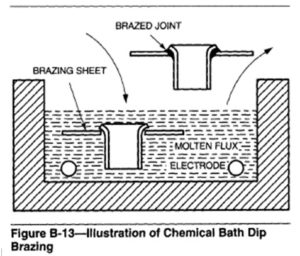
Parts should be cleaned, assembled, and preferably held in jigs prior to immersion into the bath. Brazing filler metal is preplaced as rings, washers, slugs, paste, or as a cladding on the base metal. Preheat may be necessary to assure dryness of parts and to prevent the freezing of flux on parts which may cause selective melting of flux and brazing filler metal. Preheat temperatures are usually close to the melting temperature of the flux. A certain amount of flux adheres to the assembly after brazing. Molten flux must be drained off while the parts are hot. Flux remaining on cold parts must be removed by water or by chemical means.
Infrared Brazing
Infrared brazing may be considered a form of furnace brazing, with heat supplied by long-wave light radiation. Heating is by invisible radiation from high intensity quartz lamps capable of delivering up to5000 watts of radiant energy. Heat input varies inversely as the square of the distance from the source, but the lamps are not usually shaped to follow the contour of the part to be heated. Concentrating reflectors focus the radiation on the parts. For vacuum brazing or inert-gas protection, the assembly and the lamps are placed in a bell jar or retort that can be evacuated or filled with inert gas. The assembly is then heated to a controlled temperature, as indicated by thermocouples.
Brazing Filler Metals
Brazing filler metals must have the following properties:
(1) Ability to form brazed joints with mechanical and physical properties suitable for the intended service application
(2) Melting point or melting range compatible with the base metals being joined, and sufficient fluidity at brazing temperature to flow and distribute themselves into properly prepared joints by capillary action
(3) Composition of sufficient homogeneity and stability to minimize separation of constituents (liquation) during brazing
(4) Ability to wet surfaces of base metals and form a strong, sound bond
(5) Depending on requirements, ability to produce or avoid filler-metal interactions with base metals.
To simplify filler metal selection, ANSYAWS A5.8, Specification for Brazing Filler Metal, divides filler metals into seven categories and various classifications within each category. The specification lists products which are commonly used, commercially available filler metals. Other brazing filler metals not currently covered by the specification are available for special applications.
Two sources of further information on brazing are: American Welding Society, Brazing Handbook, American Welding Society, Miami, Florida. 1991 American Welding Society, The Welding Handbook, V01.2, 8th Edition. American Welding Society, Miami, Florida. 1991.