A solid-state welding process that produces a weld by the local application of high-frequency vibratory energy as the workpieces are held together under pressure.
Ultrasonic welding produces a sound metallurgical bond without melting the base metal. The basic force in ultrasonic welding is high-intensity vibrational energy. High- frequency electrical energy is converted to mechanical vibration, and a coupler (sonotrode) transmits the vibration to the work. An anvil counters the clamping force.
This process involves complex relationships between the static clamping force, the oscillating shear forces, and a moderate temperature rise in the weld zone. The magnitudes of these factors required to produce a weld are functions of the thickness, surface condition, and the mechanical properties of the workpieces.
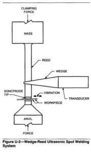
Typical components of an ultrasonic welding system are illustrated in Figure U-2. The ultrasonic vibration is generated in the transducer. This vibration is transmitted through a coupling system or sonotrode, which is represented by the wedge and reed members in Figure U-2. The sonotrode tip is the component that directly contacts one of the workpieces and transmits the vibratory energy into it. (The sonotrode is the acoustical equivalent of the electrode and its holder used in resistance spot or seam welding). The clamping force is applied through at least part of the sonotrode, which in this case is the reed member. The anvil supports the weldment and opposes the clamping force.

Applications
Ultrasonic welding is used to join both monometallic and bimetallic joints. The process is used to produce lap joints between metal sheets or foils, between wires or ribbons and flat surfaces, between crossed or parallel wires, and for joining other types of assemblies that can be supported on the anvil.
This process is being used as a production tool in the semiconductor, microcircuit, and electrioal contact industries, for fabricating small motor armatures, in the manufacture of aluminum foil, and in the assembly of aluminum components. It is receiving acceptance as a structural joining method by the automotive and aerospace industries. The process is uniquely useful for encapsulating materials such as explosives, pyrotechnics, and reactive chemicals that require hermetic sealing but cannot be processed by high-temperature joining methods.
The most important application of the USW process is the assembly of miniaturized electronics components. Fine aluminum and gold lead wires are attached to transistors, diodes, and other semiconductor devices. Wires and ribbons are bonded to thin films and microminiaturized circuits. Diode and transistor chips are mounted directly on substrates. Reliable joints with low electrical resistance are produced without contamination or thermal distortion of the components.
Electrical connections, both single and stranded wires, can be joined to other wires and to terminals. The joints are frequently made through anodized coatings on aluminum, or through certain types of electrical insulation. Other current carrying devices, such as electric motors, field coils, harnesses, transformers and capacitors may be assembled with ultrasonically welded connections.
Broken and random lengths of aluminum foil are welded in continuous seams by foil rolling mills, with almost undetectable splices after subsequent working operations. Aluminum and copper sheet up to about 0.5 mm (0.020 in.) can be spliced together using special processing and equipment.
In structural applications, USW produces joints of high integrity within the limitations of weldable sheet thickness. An example is the assembly of a helicopter access door, in which inner and outer skins of aluminum alloy are joined by multiple ultrasonic spot welds.
Ultrasonic welding has reduced fabrication costs for some solar energy conversion and collection systems. An ultrasonic seam welding machine, operating at speeds up to 9 dmin (30 ft/min), joins all connectors in a single row in a fraction of the time require for hand soldering or individual spot welding. Solar collectors for hot water heating systems consisting of copper or aluminum tubing can be welded at significantly lower energy cost than soldering, resistance spot welding, or roll welding.
Other applications include continuous seam welding to assemble components of corrugated heat exchangers, and welding strainer screens without clogging the holes. Beryllium foil windows for space radiation counters have been ring welded to stainless steel frames to provide a helium leak-tight bond. Pinch-off weld closures in copper and aluminum tubing used in refrigeration and air conditioning are produced with special serrated bar tips and anvils.
Process Variations
There are four variations of the process, based on the type of weld produced. These are spot, ring, line and continuous seam welding. In addition, two variants of ultrasonic spot welding are used in micro electronics.
Spot Welding- In spot welding, individual weld spots are produced by the momentary introduction of vibratory energy into the workpieces as they are held together under pressure between the sonotrode tip and the anvil face. The tip vibrates in a plane essentially parallel to the plane of the weld interface, perpendicular to the axis of static force application. Spot welds between sheets are roughly elliptical in shape at the interface. They can be overlapped to produce an essentially continuous weld joint. This type of seam may contain as few as 2 to 4 welds/cm (5 to 10 welds/in.). Closer weld spacing may be necessary if a leaktight joint is required.
Ring Welding- Ring welding produces a closed loop weld which is usually circular in form but may also be square, rectangular or oval. In this variation, the sonotrode tip is hollow, and the tip face is contoured to the shape of the desired weld. The tip is vibrated torsionally in a plane parallel to the weld interface. The weld is completed in a single, brief weld cycle.
Line Welding- Line welding is a variation of spot welding in which the workpieces are clamped between an anvil and a linear sonotrode tip. The tip is oscillated parallel to the plane of the weld interface and perpendicular to both the weld line and the direction of applied static force. The result is a narrow linear weld, which can be up to 150 mm (6 in.) long, produced in a single weld cycle.
Continuous Seam Welding- In this variation, joints are produced between workpieces that are passed between a rotating, disk-shaped sonotrode tip and a roller type or flat anvil. The tip may traverse the work while it is supported on a fixed anvil, or the work may be moved between the tip and a counter-rotating or traversing anvil. Area bonds may be produced by overlapping seam welds.
The flow of energy through an ultrasonic welding system begins with the introduction of 60 Hz electrical power into a frequency converter. This device converts the applied frequency to that required for the welding system, which is usually in the range of 10 to 75 kHz. The high-frequency electrical energy is conducted to one or more transducers in the welding system, where it is converted to mechanical vibratory energy of the same frequency. The vibratory energy is transmitted through the sonotrode and sonotrode tip into the workpiece. Some of the energy passes through the weld zone and dissipates in the anvil support structure.
For practical usage, the power required for welding is usually measured in terms of the high-frequency electrical power delivered to the transducer. This power can be monitored continuously and provides a reliable average value to associate with equipment performance as well as with weld quality. The product of the power in watts and welding time in deconds is the energy, in watt-seconds or joules, used in welding. The energy required to make an ultrasonic weld can be related to the hardness of the workpieces and the thickness of the part in contact with the sonotrode tip.
Process Advantages and Limitations.
Ultrasonic welding has advantages over resistance spot welding in that little heat is applied during joining and no melting of the metal occurs. This process permits welding thin to thick sections, as well as joining a wide variety of dissimilar metals. Welds can be made through certain types of surface coatings and platings. Ultrasonic welding of aluminum, copper and other high-conductivity metals requires substantially less energy than resistance welding. As compared to cold welding, the pressures used in USW are much lower, welding times are shorter, and thickness deformation is significantly lower.
A major disadvantage is that the thickness of the component adjacent to the sonotrode tip must not exceed relatively thin gauges because of the power limitations of present ultrasonic welding equipment. The range of thicknesses of a particular metal that can be welded depends on the properties of that metal. Ultrasonic welding is limited to lap joints. Butt welds cannot be made in metals because there is no effective means of supporting the workpieces and applying clamping force. However, ultrasonic butt welds are made in some polymer systems.
Safety
The welding machine operator should be provided with eye and ear protection. Most ultrasonic welding equipment is designed with interlocks and other safety devices to prevent personnel from contacting high voltages in the equipment. Nevertheless, consideration must be given to operating personnel and all personnel in the area of the welding operations. There must be strict conformance to the manufacturers’ operating instructions and safety recommendations as well as requirements in ANSI/ASC 2-49.1 (latest edition), Safety in Welding and Cutting and applicable requirements of the Occupational Safety and Health Administration (OSHA).