Welding that is performed and controlled by robotic equipment. Variations of this term are robotic brazing, robotic soldering, robotic thermal cutting, and robotic thermal spraying. See ADAEIVE CONTROL WELDING, AUTOMATIC WELDING, MANUAL WELDING, MECHANIZED WELDING, and SEMIAUTOMATIC WELDING.
Robots are used where repetitive work functions are performed. They are usually computer driven. Robotic equipment is especially useful where the work is performed in environments that are uncomfortable or hazardous, for example, material handling in the proximity of a furnace. Production welding is a good application for robotic equipment because it involves repetitive welding on parts of a given size and shape.
Robotic equipment requires special features and capabilities to successfully perform arc welding operations. Arc welding robots are generally high-precision machines containing electric servomotor drives and special interfaces with the arc welding equipment.
Programming- An automatic arc welding system must be programmed to perform the welding operation. Programming is the establishment of a detailed sequence of steps that the machine must follow to successfully weld the assembly to specifications.
Developing a welding program involves the following steps:
(1) Calibrate the automatic welding system. Calibration insures that future use of the program will operate from a known set point.
(2) Establish the location of the assembly with respect to the welding machine. Often simple fixturing is sufficient.
(3) Establish the path to be followed by the welding gun or torch as welding progresses. Some robots can be “taught” the path while other automatic welding systems have to be programmed off-line.
(4) Develop the welding conditions to be used. They must then be coordinated with the work motion program.
(5) Refine the program by checking and verifying performance. Often, a program requires editing to obtain the desired weld joint.
There are four general geometric classifications of industrial robots:
(1) Rectilinear (Cartesian coordinate) robots have linear axes, usually three in number, which move a wrist in space. Their working zone is box shaped.
(2) Cylindrical coordinate robots have one circular axis and two linear axes. Their working zone is a cylinder.
(3) Spherical coordinate robots employ two circular axes and one linear axis to move the robot wrist. Their working zone is spherical.
(4) Articulating (jointed arm) robots utilize rotary joints and motions similar to a human arm to move the robot wrist. The working zone has a irregular shape. All four robot geometries perform the same basic function: the movement of the robot wrist to a location in space. Each geometry has advantages and limita- tions under certain conditions. Articulating and rectilinear robots are favored designs for arc welding.
Robotic arc welding is applicable to high, medium, and low volume manufacturing operations under certain conditions. It can be applied to automation of medium and low volume production quantities where the total volume warrants the investment.
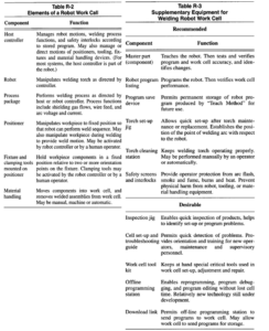
An arc welding robot requires a number of periphera1or supporting devices to achieve optimum productivity. The basic elements of a robotic work cell are shown in Table R-2. Many variations are possible, and each device could contain its own controller that would execute instructions from its program on command from the robot or host controller. All robot stations can be enhanced by one or more of the components listed in Table R-3. These components help to “teach” the robot quickly, minimize times for scheduled and unscheduled maintenance, and assure operator and equipment safety. Also included in Table R-3 are several features that are not necessary for efficient robot cell use but can enhance the productivity of the cell.

An articulating (jointed arm)robot is favored for arc welding small parts where there are long travel distances between welds. The arm of this type of robot is capable of quick motion. This robot design is also preferred for nonmovable assemblies that require the robot to reach around or inside a workpiece to position the robot wrist.
For safety reasons, rectilinear robots are favored for most other arc welding applications. They are particularly suited for applications where a welding operator is required to be in close proximity to the welding arc. Rectilinear robots move slower and in a more predictable path than articulating robots.
Axes- Arc welding robots usually have five or six axes (Figure R-12) and some may be equipped with seven or eight axes. A complete robotic work station may contain as many as eleven axes of coordinated motion.

Robot Transfer- Large assemblies and assemblies that require significant arc time can be welded by moving or rotating a robotic arc welding machine into the welding area. This procedure is usually faster than moving the assembly, but it requires a relatively large working area.
A welding robot can be transferred between multiple work stations. This allows production flexibility, and reduces inventory and material handling costs. Work stations can be left in place when not in use while the robot is utilized at other locations.
Some robots can access multiple welding stations located in a semicircle. Rectilinear robots can move to welding stations that are organized in a straight line.
Positioner- A positioner can be used to move an assembly under an automatic arc welding head during the welding operation, or to reposition an assembly, as required, for robotic arc welding. The assembly can be moved so that the welding can be performed in a favorable position, usually the flat position.
There are two types of positioners for automatic arc welding. One type indexes an assembly to a programmed welding position. The other type is incorporated into the welding system to provide an additional motion axis. A positioner can provide continuous motion of the assembly while the machine is welding, to improve cycle time. Positioners can have fully coordinated motion for positioning a weld joint in the flat position in a robot cell.
Control Interfaces- An automatic arc welding system requires control interfaces for component equipment. Two types of interfaces are usually provided: contact closures and analog interfaces.
Welding Process Equipment- Welding power sources and welding wire feeders are controlled with both electrical contact closure and analog interfaces. Contact closures are used to turn equipment on and off. Analog interfaces are used to set output levels.
Fixtures and Positioners- Fixtures for automatic welding are often automated with hydraulic or pneumatic clamping devices. The welding machine often controls the operation of the clamps. Clamps can be opened to permit gun or torch access to the weld joint. Most clamping systems and positioner movements are activated by electrical contact closures.
Offline Programming and Interfacing with Computer Aided Design. The process of “teaching” the robot can be time consuming, utilizing productive robot time. If the need of only a few parts is forecast, robotic welding may not be economical. However, off-line programming using computer-aided design (CAD) systems can be used to program the sequence of motions of the robot and the positioner. Graphic animation programs help to visualize and debug the motion sequence. The CAD model cannot always duplicate the actual conditions at the actual welding station. It is often necessary to edit any motion program generated off line.
Each assembly to be welded requires an investment in programming. Programming costs vary widely depending on the welding system being used, the experience of the programmers, and the complexity of the welding process. Investment in programrning must be taken into account when determining the economics of automatic welding. Once an investment is madefor a specific weldment the program can be stored for future use.
Safety- The operator of a robotic system can easily avoid close proximity to jagged edges of parts, weld metal expulsion, and other welding hazards. However, the movement of the robot arm creates a dangerous environment. Workers in the area must be prevented from entering the working envelope of the robot. Protective fences, power interlocks and detection devices should be installed to assure worker safety.