The removal of any unwanted gas or vapor from a container, chamber, hose, torch, or furnace. It includes the removal of remaining gases or vapors from a container that may have held flammable material, such as grease, oil or gasoline, by washing with detergents or with live steam, and subsequently filling with carbon dioxide, nitrogen or inert gas to minimize explosion hazard during hot work. Purging includes removing air
from an acetylene generator that may have entered while the generator was being charged with water and carbide.
Purging of pipe is the process of replacing the atmosphere within a pipe or tube with an inert gas atmosphere to prevent the contamination of the root bead during welding.
Satisfactory welds can be made in carbon steel pipe using consumable root insert rings without inert gas backup. However, the weld root will usually be rough and irregular, and the fused metal does not readily wet the base metal. When inert gas is used for a backup shield, the weld root will have a uniform, smooth, contour free of oxides. The fused metal will readily wet the base metal.
Total System Purging
If the use of purging dams is prohibited by code, or cannot be used for some other reason, it may be necessary to purge the entire system. In systemic purging, the ends of a pipe string are sealed off with plugs of rubber or other suitable material, and the pipe string is purged of air with inert gas, usually argon because it is heavier than air. The inert gas is introduced at one end of the string and vented at the other end through a small opening. The inlet opening should always be as low as possible and the vent as high as possible to take advantage of the different densities of air and argon.
Volume of Purging Gas Required. Purging an entire system is usually the most expensive method of purging because of the time and the volume of inert gas required. Usually a minimum of six volume changes is required to reduce the oxygen content of the purged volume to approximately 1 %. The number of volume changes of gas required to achieve a suitable degree of inertness (usually less than 1% oxygen) depends on several factors. In a gas-tight system, as few as two or three volume changes will provide an atmosphere suitable for welding stainless steel and high-nickel alloys, but only if the inert gas is introduced slowly through a diffusing device. Theoretically, if argon is introduced slowly into the bottom of a closed chamber which is vented at the top, only one volume change should be necessary to remove all the air. However, this is not possible because gas molecules are in constant motion, and some of the heavier argon will rise and mix with
the lighter air.
Analysis of a number of typical purges indicates that a minimum of ten volume changes is required to reduce the percentage of air to 0.1%. High flow rates reduce the time needed to purge a system; however, slow flow rates reduce gas consumption. If a system can be closed off and evacuated, then backfilled with inert gas, the air can be reduced to less than 0.1 % with only one volume of gas. Once a system has been purged to a suitable level, the purging gas flow rate can be reduced substantially to a value which will maintain a positive pressure and flow.
Determining Oxygen Content. One method of determining the quality of the chamber or pipe atmosphere is to exhaust a sample of the gas through an oxygen analyzer. This provides a quick and accurate indication of the oxygen content, which will indicate whether the atmosphere is satisfactory for welding. If a gas analyzer is not available, flow rate charts can be used which indicate flow rates and times required to purge a given size chamber to 1% or less oxygen.
Purging Dams
Purging dams are plugs made of a variety of materials which are placed inside tubing or piping at both sides of a joint to be welded. These dams isolate the weld joint so that only the root of the weld zone needs to be shielded with inert gas rather than the whole pipe string. Some of the more commonly used systems are described in the following sections.
Soluble Dams. Soluble dams are constructed of a material which can be dissolved in a liquid, and are available commercially in the form of discs cut to fit the ID’S of standard pipe sizes. The discs have the texture of heavy paper and sufficient strength to resist the
slight pressures used for purging. The discs are placed in the two pieces of pipe to be joined, as close to the joint as the estimated maximum temperature will permit, and cemented in place with water soluble cement. A typical distance from disc to joint is 15.2 to 30.4 cm (6 to 12 inches).
The inert gas is usually introduced to the weld purge zone through small diameter tubing inserted into the center of the joint preparation or through one of the discs. Large pipe may require more than one purge tube for adequate purging. After welding, the dam can be removed by flushing with water, which dissolves all dam material. See Figure P-22 (A).
Inflatable Bladder Dam. Inflatable bladders are made of rubberized fabric, or a flexible plastic which will not soften or melt at slightly elevated temperatures. They have been used for many years in the repair and modification of low-pressure natural gas piping. An
advantage of bladders is that they can be collapsed to permit insertion into the pipe through a relatively small opening. The collapsed bladders are positioned in the pipe at the desired location and inflated, generally with the same gas used for purging. The gas used to inflate the bladders and for purging is introduced through a set of hoses passing through the open end of the pipe string. These are removed through the open end after welding. It is important to note that the bladder type dam can only be removed through an open end of the pipe string while soluble dams can be dissolved and thus removed through a small opening in the pipe string. See Figure P-22 (B).
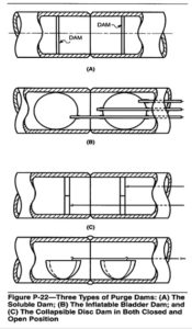
Collapsible Disc Dam. Collapsible disc dams are the simplest and least expensive dam system. The discs may be fabricated from one-inch plywood or similar material, are hinged across the middle and are fitted with a thick band of foam rubber, or similar material, around the rim to provide a gas-tight seal with the pipe inside diameter. A chain attached to one side of the disc is positioned so that a tug will collapse the disc and rotate it so that it can be pulled out through the pipe’s open end. The collapsible discs must be positioned in the pipe ends before they are brought together. See Figure P-22 (C).