A resistance welding process that produces a weld by the heat obtained from the resistance to the flow of the welding current. The resulting welds are localized at predetermined points by projections, embossments, or intersections. See RESISTANCE WELDING.
As with spot and seam welding, projection welding can be used to produce lap joints. The purpose of a projection is to localize the heat and pressure at a specific point on the joint. The number and shape of the projections depend upon the requirements for joint strength.
Circular or annular ring projections can be used to weld parts requiring either gas-tight or water-tight seals, or to obtain a larger area weld than button-type projections can provide.
Projection Designs
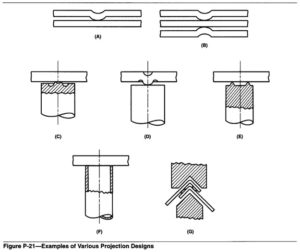
The projection design determines the current density. Various types of projection designs are shown in Figure P-2 1.
The method of producing projections depends on the material in which they are to be produced. Projections in sheet metal parts are generally made by embossing, as opposed to projections formed in solid metal .pieces which are made by either machining or forging. In the case of stamped parts, projections are generally located on the edge of the stamping.
Applications
Projection welding is primarily used to join a stamped, forged, or machined part to another part. One or more projections are produced on the parts during
the forming operations. Fasteners or mounting devices, such as bolts, nuts, pins, brackets, and handles, can be projection-welded to a sheet metal part. Projection welding is especially useful for producing several weld nuggets simultaneously between two
parts. Marking of one part can be minimized by placing the projections on the other part.
The process is generally used for section thicknesses ranging from 0.5 to 3.2 mm (0.02 to 0.125 in.) thick. Thinner sections require special welding machines capable of following the rapid collapse of the projections. Various carbon and alloy steels and
some nickel alloys can be projection welded.
Advantages and Limitations
In general, projection welding can be used instead of spot welding to join small parts to each other and to larger parts. Selection of one method over another depends on the economics, advantages, and limitations of the two processes. The chief advantages of projection welding include the following:
(1)A number of welds can be made simultaneously in one welding cycle of the machine. The limitation on the number of welds is the ability to apply uniformelectrode force and welding current to each projection.
(2) Less overlap and closer weld spacings are possible, because the current is concentrated by the projection, and shunting through adjacent welds is not a problem.
(3) Thickness ratios of at least 6 to 1 are possible, because of the flexibility in projection size and location. The projections are normally placed on the thicker section.
(4) Projection welds can be located with greater accuracy and consistency than spot welds, and the welds are generally more consistent because of the uniformity of the projections. As a result, projection welds can be smaller in size than spot welds.
(5) Projection welding generally results in better appearance, on the side without the projection, than spot welding can produce. The most deformation and greatest temperature rise occur in the part with the projection, leaving the other part relatively cool and free of distortion, particularly on the exposed surface.
(6) Large, flat-faced electrodes are used; consequently, electrode wear is much less than that with spot welding and this reduces maintenance costs. In some cases, the fixturing or part locators are, combined with the welding dies or electrodes when joining small parts together.
(7) Oil, rust, scale, and coatings are less of a problem than with spot welding because the tip of the projection tends to break through the foreign material early in the welding cycle; however, weld quality will be better with clean surfaces.
The most important limitations of projection welding are the following:
(1) The forming of projections may require an additional operation unless the parts are press-formed to design shape.
(2) With multiple welds, accurate control of projection height and precise alignment of the welding dies are necessary to equalize the electrode force and welding current.
(3) With sheet metal, the process is limited to thicknesses in which projections with acceptable characteristics can be formed, and for which suitable welding equipment is available.
(4)Multiple welds must be made simultaneously, which requires higher capacity equipment than does spot welding. This also limits the practical size of the component that contains the projections.