An arc welding process that uses a constricted arc between a nonconsumable electrode and the weld pool (transferred arc) orbetween the electrode and the constricting nozzle (nontransferred arc). Shielding is obtained from the ionized gas issuing from the torch, which may be supplemented by an auxiliary source of shielding gas. The process is used without the application of pressure. See also HOT WIRE WELDING.
Historical Background
One of the earliest plasma arc systems was a gas vortex stabilized device introduced by Schonherr in 1909. In this unit, gas was blown tangentially into a tube through which an arc was struck. The centrifugal force of the gas stabilized the arc along the axis of the tube by creating a low pressure axial core. Arcs up to several meters in length were produced, and the system proved useful for arc studies.
Gerdien and Lotz built a water vortex arc-stabilizing device in 1922. In this device, water injected tangentially into the center of a tube was swirled around the inner surface and ejected at the ends. When an arc struck between carbon electrodes was passed through the tube, the water concentrated the arc along its axis, producing higher current densities and temperatures than were otherwise available. The Gerdien and Lotz
invention had no practical metalworking applications because of the rapid consumption of its carbon electrodes and the presence of water vapor in the plasma jets.
While working on the arc melting of refractoly metals in 1953, R. M. Gage, U.S. Patent No. 2 806 124, observed the similarity in appearance between a long electric arc and an ordinary gas flame. Efforts to control the heat intensity and velocity of the arc led to the development of the modem plasma arc torch.
The first practical plasma arc metal-working tool was a cutting torch introduced in 1955. This device was similar to a gas tungsten arc welding torch in that it used a tungsten electrode and a “plasma” gas. However, the electrode was recessed in the torch, and the arc was constricted by passing it through an orifice in the torch nozzle. The usual circuitry for gas tungsten arc welding was supplemented in the plasma arc cutting torch with a pilot arc circuit for arc initiation.
Principles of Operation
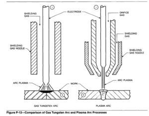
The plasma arc process can be considered as an extension of the gas tungsten arc welding process. However, the plasma arc processes have a much higher arc energy density and higher gas velocity as a result of the arc plasma being forced through a
constricting nozzle. See Figure P-12 for a comparison of the gas tungsten arc and plasma arc welding torch configurations. A plasma arc welding torch consists of a central tungsten electrode, a constricting nozzle with a small orifice and an outer gas nozzle which supplies shielding gas to the material being welded.
As the orifice gas passes through the plenum chamber of the plasma torch, it is heated by the arc, expands and exits through the constricting orifice at high velocity. Since too powerful a gas jet can cause turbulence in the weld puddle, orifice gas flow rates are generally held to within 0.25 to 5 L/min (0.5 to 10 cu ft/hr). The orifice gas alone is not normally adequate to shield the weld pool from atmospheric contamination, therefore auxiliary shielding gas is provided through an outer gas nozzle. Typical shielding gas flow rates are in the range of 10to 30 L/min (20 to 60 cu ft /hr).
The degree of arc collimation, arc force, energy density on the workpiece and other characteristics are primarily functions of the following:
(1) Plasma current
(2) Orifice diameter and shape
(3) Type of orifice gas
(4) Flow rate of orifice gas
The fundamental differences among the plasma arc metalworking processes, arise from the relationship of these four factors. They can be adjusted to provide very high or very low thermal energies. The very high flow rates may result in turbulence and perhaps
remove the melted metal from a groove. Therefore, the high energy densities, small orifice diameters and high jet velocities are used for cutting. For welding, a low plasma jet velocity is necessary to prevent expulsion of the molten metal from the groove. This is accomplished by using larger orifice diameters, lower plasma gas flow rates, and lower currents than normally used for cutting.
Plasma arc welding is normally done with direct current electrode negative (DCEN), pure tungsten or tungsten alloy electrodes, argon plasma gas and a transferred arc. Current range for plasma arc welding is from 0.1 to 500 amperes, depending on the torch size and material thickness. Steel, stainless steel, nickel base alloys and titanium alloys can be welded with DCEN.
Direct current electrode positive (DCEP) is used to a limited extent for welding aluminum and magnesium to make use of the surface oxide removal feature (sputtering) of this polarity. Arc current is usually limited to a maximum of 100 amperes to prevent rapid deterioration of the electrode.
Sine wave alternating current with continuous high-frequency stabilization can also be used for welding aluminum and magnesium, but the maximum is still limited to about 100 amperes. Surface oxide removal occurs during the positive half cycles of alternating current.
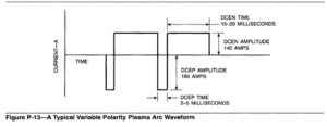
Square-wave alternating current with unbalanced positive and negative current half cycles, also called variable polarity plasma arc (VPPA), is highly efficient for welding aluminum and magnesium alloys and permits use of higher average weld current than sine wave ac. This is possible because the duration of the negative portion is considerably longer than the positive portion, thus developing most of the heat at the work, where it is needed. The short positive pulse is sufficient for removing surface oxides and does not cause excessive heating of the electrode. Good results were obtained with 15 to 20 milliseconds DCEN and 2 to 5 milliseconds DCEP. Shorter DCEP times were not effective; longer times caused electrode deterioration. A typical VPPA waveform is shown in Figure P-13.
Key hole Welding Technique
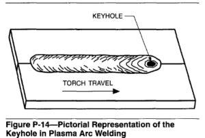
Plasma arc welding can be performed in either the melt-in or keyhole mode. The melt-in mode is similar to the gas tungsten arc process but the arc has greater stiffness and heat concentration; permitting narrower beads and less distortion than GTAW. In the keyhole mode, a stiffer, higher current density arc is used, which produces a small hole completely through the joint being welded. Figure P-14 is a pictorial representation of the keyhole in plasma arc welding. The keyhole technique is generally performed in the downhand position on material thicknesses ranging from 1.6 to 9.5 mm (1/16 to 3/8 in.). However, using appropriate welding conditions on certain metal thicknesses, keyhole welding can be done in any position. The principal advantage of keyhole welding is making welds in a single pass. As the plasma arc moves along the joint, the melted metal flows back into the hole to make the weld. If the arc moves too rapidly, the result will be cutting instead of welding.
Advantages and Limitations
Advantages. The low-current and high-current (melt-in) modes have the following advantages over gas tungsten arc welding:
(1) Energy concentration is greater, with the result that:
(a) Welding speeds are higher in some applications.
(b) Lower current is needed to produce a given weld and results in less shrinkage. Distortion may be reduced by as much as 50%.
(c) Penetration can be controlled by adjusting welding variables.
(2) Arc stability is improved.
(3) Arc column has greater directional stability.
(4) Narrower beads (higher depth-to-width ratio) for a given penetration, resulting in less distortion.
(5) Need for fixturing is less for some applications.
(6) Where the addition of filler metal is desirable, this operation is much easier since torch standoff distance is generous and the electrode cannot touch the filler or puddle. This also results in less downtime for tungsten repointing and eliminates tungsten contamination of the weld.
(7) Reasonable variations in torch standoff distance have little effect on bead width or heat concentration at the work; this makes out-of-position welding much easier.
Limitations. Some of the limitations associated with low-current and high-current (melt-in) plasma arc welding include:
(1) Due to the narrow constricted arc, the process has little tolerance for joint misalignment.
(2) Manual plasma welding torches are generally more difficult to manipulate than a comparable GTAW torch.
Equipment
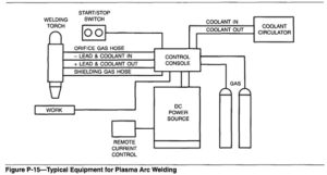
The basic equipment for plasma arc welding is shown in Figure P-15. Plasma arc welding is done with both manual and mechanized equipment.
A complete system for manual plasma arc welding consists of a torch, control console, power source, orifice and shielding gas supplies, source of torch coolant, and accessories such as gas flow timers and remote current control. Equipment is available for operation in the current range of 0.1 to 225 A, DCEN.
Mechanized equipment must be used to achieve the high welding speeds and deep penetration advantages associated with high-current plasma arc welding. A typical mechanized installation consists of a power source, control unit, machine welding torch, torch stand or travel carriage, coolant source, high-frequency power generator, and supplies of shielding gases. Accessory units such as an arc voltage control and filler wire feed system may be used as required. Machine welding torches are available for welding
with currents up to 500 A, DCEN.
Accessory Equipment
Wire Feeders. As with the GTAW process, conventional filler wire feed systems can be used with the PAW process. The filler metal is added to the leading edge of the weld pool or the keyhole at a predetermined feed rate. A wire feed system may alleviate occurrences of undercut or underfill when welding thicker materials.
Hot wire feed systems may also be used and should be fed into the trailing edge of the weld pool. Initiation and termination of wire feed may be controlled and programmed with automatic welding equipment.
Positioning Equipment. Positioning equipment for PAW is similar to that used for GTAW. Depending on the application, either the workpiece may be manipulated or the torch motion can be controlled. Workpiece manipulation generally involves a rotary positioner with the capability of tilt control. Moving the torch while the workpiece remains stationary requires a carriage on tracks or a side beam carriage for following linear joints. Combining the movement of the torch and workpiece as a system would require the use of computer programming for coordinating the operations.
Materials
Base Metals. The plasma arc welding process can be used to join all metals weldable by the GTAW process. Most material thicknesses from 0.3 to 6.4 mm (0.01to 0.25 in.) can be welded in one pass with a transferred arc. All metals except aluminum and magnesium and their alloys are welded with DCEN. Square-wave ac is used to effectively remove refractory oxides when welding aluminum and magnesium. Alternating current welding reduces the current capacity of the electrode unless the power source is capable of minimizing the duration of the positive electrode cycle. One pass keyhole welds can be made in aluminum alloys up to 12.7 mm (1/2 in.) thick. Metallurgical effects of the heat from the plasma and gas tungsten arc welding processes are similar, except the smaller
diameter plasma arc will usually melt less base metal, resulting in narrower and deeper penetration. Preheat, postheat, and gas shielding procedures are similar for both processes. Each base material has its requirements that maximize weld quality.
Consumables
Filler Metals. Filler metals used to weld the work base materials are the same as those used with the GTAW and GMAW processes. They are added in rod form for manual welding or wire form for mechanized welding. Table P-4 lists the AWS specifications for
appropriate filler metals.
Electrodes. The electrode is the same as used for gas tungsten arc welding. Pure tungsten rods and tungsten with small additions of thoria, zirconia, lanthanum, or ceria may be used for DCEN welding.
Electrodes are made to ANSUAWS A5.12, Specification for Tungsten Arc Welding Electrodes. Pure tungsten electrodes are generally selected for a-c welding.
Gases. The choice of gases to be used for plasma arc welding depends on the metal to be welded. For many PAW applications, the shielding gas is often the same as the orifice gas. Typical gases used to weld various metals are shown in Table P-5, Gas Selection
Guide for High Current Plasma Arc Welding. The shielding gases are generally inert. Active shielding gas can be used if it does not adversely affect the weld properties.

Safety Recommendations
For detailed safety information, refer to the manufacturer’s instructions and the latest edition of ANSI 249.1, Safety in Welding and Cutting. For mandatory federal safety regulations established by the U.S. Labor Department’s Occupational Safety and Health Administration, refer to the latest edition of OSHA Standards, Code of Federal Regulations, Title 29 Part 1910, available from the Superintendent of Documents, U.S. Printing Office, Washington, D.C. 20402.