An oxyfuel gas welding process that uses acetylene as the fuel gas. The process is used without the application of pressure.
Historical Background
By 1895, when Willson had established facilities to produce calcium carbide, acetylene became recognized as an important illuminating and heating gas. In about 1900, a Frenchman, Edmund Fouche, invented the oxyacetylene torch. It was a high-pressure torch which used a mixture of oxygen and acetylene, both available compressed in cylinders, the acetylene stabilized with acetone. Later, when Fouche changed jobs
and went to work for a company which produced acetylene from low-pressure generators, Fouche designed a torch that would work on low fuel gas pressures. This torch received oxygen under high pressure, which entered the mixing chamber of the torch and drew
acetylene from the acetylene orifice by the injector principle. These early torches incorporated the principles that are still used in modem low- and medium-pressure welding torches.
When Eugene Bournonville brought the first welding torch to the United States in 1906, welders began to find commercial applications for welding, and a major industry was started.
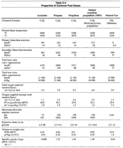
Acetylene is the fuel gas preferred for many oxyfuel welding applications because of its high-combustion intensity. Acetylene is a hydrocarbon compound, C2H2, which contains a larger percentage of carbon by weight than any of the other hydrocarbon fuel gases. Colorless and lighter than air, it has a distinctive odor resembling garlic. To stabilize acetylene in cylinders, it is dissolved in acetone; therefore it has a slightly different odor than pure acetylene.
At temperatures above 780°C (1435oF), or at pressures above 207 kPa (30 psig), gaseous acetylene is unstable, and even in the absence of oxygen, decomposition may result. This characteristic has been taken into consideration in the preparation of a code of safe practices for the generation, distribution, and use of acetylene gas. The accepted safe practice is never to use acetylene at pressures exceeding 103 kPa (15 psi) in generators, pipelines or hoses.
Theoretically, the complete combustion of acetylene is represented by the chemical equation:
C2H2+ 2.5 O232C02+ H20 (Equation 0-1)
This equation indicates that one volume of acetylene (C2H2) and 2.5 volumes of oxygen (02)react to produce two volumes of carbon dioxide (C02) and one volume of water vapor (H20).The volumetric ratio of oxygen to acetylene is 2.5 to one.
Note that the reaction of this equation does not proceed directly to the end products shown. Combustion takes place in two stages. The primary reaction takes place in the inner zone of the flame (called the inner cone) and is represented by the chemical equation:
C2H2 + 02 +2CO + H2 (Equation 0-2)
Here, one volume of acetylene and one volume of oxygen react to form two volumes of carbon monoxide and one volume of hydrogen. The heat content and
high temperature of this reaction result from the decomposition of the acetylene and the partial oxidation of the carbon resulting from that decomposition. See Table 0-2.
When the gases issuing from the torch tip are in the one-to-one ratio indicated in Equation 0-2, the reaction produces the typical brilliant blue inner cone in the flame. This relatively small flame creates the combustion intensity needed for welding steel. The flame is termed neutral because there is no excess carbon or oxygen to carburize or oxidize the metal. The end products are actually in a reducing status, a benefit when welding steel.
In the outer envelope of the flame, the carbon monoxide and hydrogen produced by the primary reaction bum with oxygen from the surrounding air. This forms carbon dioxide and water vapor, as shown in the following secondary reaction:
2CO + H2+ 1.5 02 +2C02+ H20 (Equation 0-3)
Although the heat of combustion of this outer flame is greater than that of the inner, its combustion intensity and temperature are lower because of its large cross sectional area. The final end products are produced in the outer flame because they cannot exist in the high temperature of the inner cone.
The oxyacetylene flame is easily controlled by valves on the welding torch. By a slight change in the proportions of oxygen and acetylene flowing through the torch, the chemical characteristics in the inner zone of the flame and the resulting action of the inner cone on the molten metal can be varied over a wide range. Thus, by adjusting the torch valves, it is possible to produce a neutral, oxidizing, or carburizing flame.
Equipment
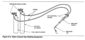
The minimum basic equipment needed to perform oxyfuel gas welding is shown schematically in Figure 0-2. This equipment setup is completely self-sufficient and relatively inexpensive. It consists of fuel gas and oxygen cylinders, each with a gas regulator for reducing cylinder pressure, hoses for conveying the gases to the torch, and a torch and tip combination for adjusting the gas mixtures and producing the desired flame.
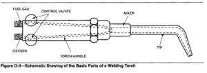
Welding Torches. A typical welding torch consists of a torch handle, mixer and tip assembly. It provides a means of independently controlling the flow of each gas, a method of attaching a variety of welding tips or other apparatus, and a convenient handle for controlling the movement and direction of the flame. Figure 0-3 is a simplified schematic drawing of the basic elements of a welding torch.
The gases pass through the control valves, through separate passages in the torch handle, and to the torch head. They then pass into a mixer assembly where the
oxygen and fuel gas are mixed, and finally pass out through an orifice at the end of the tip. The tip is shown as a simple tube, narrowed at the front end to produce a suitable welding cone. Sealing rings or surfaces are provided in the torch head or on the mixer
seats to facilitate leak-tight assembly.
Torch Handles. Welding torch handles are manufactured in a variety of styles and sizes, from the small size for extremely light (low gas flow) work to the extra heavy (high gas flow) handles generally used for localized heating operations.
A typical small welding torch used for sheet metal welding will pass acetylene at volumetric rates ranging from about 0.007 to 1.0 m3/h (0.25 to 35 ft3/h). Medium sized torches are designed to provide acetylene flows from about 0.028 to 2.8 m3/h (1 to 100ft3/h). Heavy-duty heating torches may permit acetylene flows as high as 11 m3/h (400 ft3/h). Fuel gases other than acetylene may be used with even larger torches that have fuel-gas flow rates as high as 17 m3/h (600 ft3/h).
Mixers. The chief function of the mixer is to thoroughly mix the fuel gas and oxygen to assure smooth combustion. Another function of the mixer is to serve as a heat sink to help prevent the flame from flashing back into the mixer or torch.
Two general types of oxygen fuel-gas mixers are the positive pressure (also called equal or medium-pressure) and the injector or low-pressure. The positive pressure mixer requires the gases to be delivered to the torch at pressures above 14 kPa (2 psig). In the
case of acetylene, the pressure should be between 14 and 103 kPa (2 and 15 psig). Oxygen is generally supplied at approximately the same pressure. There is, however, no restrictive limit on the oxygen pressure. It can range up to 172 kPa(25 psig) with the larger sized tips.
The purpose of the injector-type mixer is to increase the effective use of fuel gases supplied at pressures of 14 kPa (2 psig) or lower. In this torch, oxygen is supplied at pressures ranging from 70 to 275 kPa (10 to 40 psig), the pressure increasing to match the tip size. The relatively high velocity of the oxygen flow is used to aspirate, or draw in, more fuel gas than would normally flow at the low supply pressures.
Setting Up Equipment
It is essential that the operator follow the correct sequence in setting up equipment.
Connecting the Regulator. The first step is to slightly open the oxygen cylinder, then immediately close it.
This is sometimes called “cracking the valve”, which blows away any dust that might be in the cylinder valve nipple. The regulator is then connected to the cylinder, with the regulator adjustment screw turned fully counterclockwise. The valve should then be slowly opened. If the valve were opened suddenly, 13.8 MPa (2000 psi) of pressure would enter the regulator with a violent rush. If the regulator adjustment screw should happen to be screwed in, thus forcing the valve seat to the open position, it would be quickly and violently snapped back into the closed position, which might damage the seat or the nozzle, through which the oxygen passes. It is also possible under certain circumstances with certain types of regulators, to raise the temperature at the seat enough to ignite the hard rubber seat and thus create too much pressure in the regulator, damaging the gauges and the mechanism itself.
While the pressure in the acetylene cylinder is much lower than in the oxygen cylinder, and there is not the same likelihood of damage to the regulator, pressure should always be turned on slowly and carefully.
Hose Connections. Hoses should be connected to the outlet fittings of both regulators. The oxygen hose has right-hand threads on each end and the acetylene hose has left-hand fittings.
Torch Valves. Before connecting either hose line to the torch, it is important to check to see that both torch valves are closed. When the hose connections have been tightened and it has been determined that none of the joints leak, the correct size tip for the work should be screwed into the torch. The adjustment screw of the acetylene regulator should be turned to the right until the correct pressure of acetylene for the tip in use shows on the low-pressure gauge of the regulator. This is done with only the acetylene torch valve open; the oxygen torch valve remains closed. The acetylene torch valve is then closed.
The oxygen torch valve is opened and the adjustment screw of the oxygen regulator turned to the right until the correct pressure of oxygen for the tip in use is
shown on the low-pressure gauge of the oxygen regulator. The oxygen torch valve is then closed. There is now pressure of both gases in the two hose lines, and in the torch up to the torch valves. To light the torch, the acetylene valve is opened and the acetylene lighted with a flint scratch lighter as it issues from the torch tip. The oxygen valve is then opened, permitting the oxygen pressure to enter the torch and burn with the acetylene at the tip, where it forms a luminous cone of flame. Further adjustment may now be made to assure that the flame is exactly neutral, and that the regulator pressures, when the torch valves are open and the flame is burning, are correct.
It is important to have regulators with two gauges, one showing the pressure of the gas in the cylinder, and the other showing the pressure of the gas in the hose line to the torch. These gauges should always be in good condition, and the regulator should never be used if the gauges are broken. Dangerous pressures can very easily develop in the hose lines if broken or inaccurate gauges are used.
Types of Torches. A number of different types of torches are available, designated by the relative pressures of the two gases. For example, the low-pressure or injector torch supplies acetylene to the torch at a pressure of less than 14 kPa (2 psi). This pressure is
constant for most tip sizes. The oxygen pressure is considerably higher, ranging from 70 to 206 kPa (10 to 30 psi) or more, depending on the tip size. The tip is designed with an injector nozzle through which the oxygen passes, drawing the acetylene through the
torch and to the mixing chamber in the tip. This necessitates a very small opening for the oxygen through the injector nozzle, and a much larger opening for acetylene adjacent to the mixing chamber because of the difference in the pressures of the two gases. Low pressure torches are designed with unequal area inlets to the mixing chamber so that the oxygen pressure is often twice the acetylene pressure.
Equal pressure torches are those designed with equal area inlets to the mixing chamber of the tip for both oxygen and acetylene. Both gases are delivered from the regulators at equal pressures.
Another type of torch with an acetylene opening slightly smaller than the oxygen opening delivers the acetylene to the mixing chamber at a pressure slightly greater than the oxygen pressure.
All torches are designed to deliver one part oxygen through the torch for each part of acetylene entering through the acetylene passage. While it is true that 2-1/2 volumes of oxygen are required to completely consume one volume of acetylene, only one of these volumes is delivered through the torch, and burns at the tip of the torch to produce the luminous cone of flame, and the secondary reaction, the flame envelope. The remaining 1-1/2 parts of oxygen are obtained from the surrounding air.
Tip Size. Torch tips are interchangeable and are made in various sizes to produce large or smaller flames as may be required for the thickness of the workpiece. A very light sheet of steel, for example, requires a very small flame, hence a small tip, while a piece of 25 mm (1 in.) steel plate requires a much larger tip. The various sizes of tips deliver varying
pressures of both oxygen and acetylene.
Some welders tend to increase the regulator pressure and adjust the torch valves to cut down the volume of gases which pass through the torch. This is not a good practice because it may lead to a careless adjustment of the flame. Accurate maintenance of a
neutral, oxidizing, or carburizing torch flame, as required for the metal being welded, is important.
Auxiliary equipment includes protective clothing, helmet, goggles with protective lenses, and gloves. Before welding, it is imperative that the welding operator read and understand safety precautions related to oxyacetylene welding.
The Welding Process. Oxygen and acetylene are delivered through the hose lines to the torch, and are adjusted for either neutral, oxidizing, or carburizing flames, depending on the metal to be welded. The adjustment of the flame is probably the most critical condition of oxyacetylene welding. The welds are made by a torch (or blow pipe) flame to heat the workpiece to the melting point. Usually some new metal is added from a welding rod which is melted at the time and flowed together with the fused metal of the two edges of the joint. The temperature of the flame produced by the oxygen and acetylene delivered through the torch is in the range of 3200 to 3480°C (5800 to
6300°F).
The diameter of the welding rod to be used depends on the thickness of the workpiece. The rod maybe straight or bent to an angle as necessary. If the edges are to be beveled, the workpieces should be prepared with either a single or double V, forming a deep U shape, or in the case of sheet metal, flanging the edges upward. See BEVELING.
Welding proceeds either forward (away from the operator), or backward (toward the operator), depending on the required procedure. The motion of the torch depends on the operator; sometimes the flame is moved in a semi-circle and the rod straight back and
forth immediately ahead of the flame in alternating motions.
Welding Rods. It is essential that the correct welding rod be used to insure weld integrity. The American Welding Society (AWS) filler metal specifications should be consulted for the recommended materials. Additionally, the manufacturer of the material to be
welded, as well as the manufacturer of appropriate filler metals, are excellent sources of information concerning proper welding procedures and appropriate filler metals.