An arc cutting process that uses a single tungsten electrode with gas shielding.
This process used a standard GTAW torch with a small diameter shielding cup, high arc current, DCEN, and gas flow rates in the range of 25 L/min (50 ft3/h) to sever metals. It is generally considered a temporary procedure.
Principles of Operation
Gas tungsten arc cutting can be used to sever non-ferrous metals and stainless steel in thicknesses up to 1/2 in. using standard gas tungsten arc welding equipment. Metals cut include aluminum, magnesium, copper, silicon-bronze, nickel, copper-nickel, and various types of stainless steels. This cutting process can be used either manually or mechanized. The same electric circuit is used for cutting as for welding. Higher current is required to cut a given thickness of plate than to weld it. An increased gas flow is also required to melt through and sever the plate. In practice, a 4 mm (5/32 in.) diameter, 2% thoriated tungsten electrode is extended approximately 6 mm (1/4 in.) beyond the end of a 9.5 mm (3/8 in.) diameter metallic or ceramic gas cup. A mixture of approximately 65% argon and 35% hydrogen is delivered to the torch at a flow rate of 30 L/min (60 ft3/h).
Nitrogen can also be used, but the quality of the cut is not as good as that obtained with an argon-hydrogen mixture. Best cutting results are obtained using DCSP, but alternating current with superimposed high frequency has produced satisfactory cuts on material up
to 6 mm (1/4 in.) thick.
Arc starting can be accomplished with either a high frequency spark or by scratching the electrode on the workpiece. An electrode-to-work distance of 1.6 to 3.2
mm (1/16 to 118 in.) is used, but this is not a critical factor. As the torch is moved over the plate, a small section of the plate is melted by the heat of the arc and the molten metal is blown away by the gas stream to form the kerf. At the end of the cut, the torch is raised
from the workpiece to break the arc.
One face of the cut is usually dross-free, with dross adhering to the side of the workpiece away from the work lead. The cut quality on the dross-free side is usually acceptable while the other requires considerable cleanup.
Equipment
Standard gas tungsten arc welding torches can be used for cutting. Cutting currents up to 600 amperes are used. Welding torches can be used for cutting at
currents up to 175% of their nominal ratings because there is little reflected heat from the cutting operation. For example, a 300-ampere torch can be used for cutting with 500 amperes for short periods.
A constant-current d-c power supply with a minimum open circuit voltage of 70 V is recommended for cutting. Cuts made with a-c power have a plate thickness limitation of 6 mm (1/4 in.). The major difficulty encountered when using a-c power is the loss of tungsten from the electrode at the high currents required.
GAS TUNGSTEN ARC CUTTING TORCH
A device used to transfer current to a fixed cutting electrode, position the electrode, and direct the flow of shielding gas.
GAS TUNGSTEN ARC WELDING (GTAW)
An arc welding process that uses an arc between a tungsten electrode (non consumable) and the weld pool. The process is used with shielding gas and with-
out the application of pressure. See also HOT WIRE WELDING and PULSED
GAS TUNGSTEN ARC WELDING.
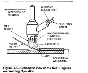
Gas tungsten arc welding (GTAW) may be used with or without the addition of filler metal. Figure G-8 shows the gas tungsten arc welding process.
GTAW has become indispensable as a tool for many industries because of the high-quality welds produced and low equipment costs. The following information
presents the fundamentals of the GTAW process, the equipment and consumables used, the process procedures and variables, applications, and safety considerations.
Historical Background
The possibility of using helium to shield a welding arc and molten weld pool was first investigated in the 1920s. However, little was done with this method until the beginning of World War 11, when a great need developed in the aircraft industry to replace riveting for joining reactive materials such as aluminum and magnesium. Using a tungsten electrode and direct current arc power with the electrode negative, a stable,
efficient heat source was produced with which excellent welds could be made.
Since the early days of the invention, numerous improvements have been made to the process and equipment. Welding power sources have been developed specifically for the process. Some provide pulsed dc and variable-polarity a-c welding power. Water cooled and gas-cooled torches were developed. The tungsten electrode has been alloyed with small amounts of active elements to increase its emissivity; this has improved arc starting, arc stability, and electrode life. Shielding gas mixtures have been identified for improved welding performance.
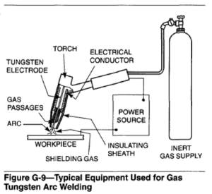
Typical equipment used for the gas tungsten arc welding process is illustrated in Figure G-9. The process uses a nonconsumable tungsten (or tungsten alloy) electrode held in a torch. Shielding gas is fed through the torch to protect the electrode, molten weld pool, and solidifying weld metal from contamination by the atmosphere. The electric arc is produced by the passage of current through the conductive, ionized
shielding gas. The arc is established between the tip of the electrode and the work. Heat generated by the arc melts the base metal. Once the arc and weld pool are established, the torch is moved along the joint and the arc progressively melts the faying surfaces. Filler wire, if used, is usually added to the leading edge of the weld pool to fill the joint.
Advantages
The following are some advantages of the gas tungsten arc process:
(1) It produces superior quality welds, generally free of defects.
(2) It is free of the spatter which occurs with other arc welding processes.
(3) It can be used with or without filler metal as required for the specific application.
(4) It allows excellent control of root pass weld penetration.
(5)It can produce inexpensive autogenous welds at high speeds.
(6) It can use relatively inexpensive power supplies.
(7) It allows precise control of the welding variables.
(8) It can be used to weld almost all metals, including dissimilar metal joints.
(9) It allows the heat source and filler metal additions to be controlled independently.
Limitations
The following are some limitations of the gas tungsten arc process:
(1)Deposition rates are lower than the rates possible with consumable electrode arc welding processes.
(2) There is a need for slightly more dexterity and welder coordination than with gas metal arc welding or shielded metal arc welding for manual welding.
(3) It is less economical than the consumable electrode arc welding processes for sections thicker then 10mm (3/8 in.).
(4)There is difficulty in shielding the weld zone properly in drafty environments.
Potential problems with the process include:
(1)Tungsten inclusions can occur if the electrode is allowed to contact the weld pool.
(2) Contamination of the weld metal can occur if proper shielding of the filler metal by the gas stream is not maintained.
(3)There is low tolerance for contaminants on filler or base metals.
(4)Possible contamination or porosity can be caused by coolant leakage from water-cooled torches.
(5) Arc blow or arc deflection, as with other processes.
This process has been called Heliarc (a registered trade mark of Union Carbide Corporation), named for the helium shielding gas originally used, and TIG (tungsten inert gas) welding, However, the AWS terminology for this process is, gas tungsten arc welding (GTAW), because shielding gas mixtures which are not inert can be used for certain applications.
Process Variables
The primary variables in GTAW are arc voltage (arc length), welding current, travel speed, and shielding gas. The amount of energy produced by the arc is proportional to the current and voltage. The amount transferred per unit length of weld is inversely proportional to the travel speed. The arc in helium is more penetrating than that in argon. However, because all of these variables interact strongly, it is impossible to treat them as truly independent variables when establishing welding procedures for fabricating specific joints.
Arc Current. As a general statement, arc current controls the weld penetration, the effect being directly proportional, if not somewhat exponential. Arc current also affects the voltage, with the voltage at a fixed arc length increasing in proportion to the current. For this reason, to keep a fixed arc length, it is necessary to change the voltage setting when the current is adjusted.
The process can be used with either direct or alternating current, the choice depending largely on the metal to be welded. Direct current with the electrode negative (DCEN) offers the advantages of deep penetration and fast welding speeds, especially when helium is used as the shield. Helium is the gas of choice for mechanized welding.
Alternating current provides a cathodic cleaning (sputtering) which removes refractory oxides from the surfaces of aluminum and magnesium during the portion of the a-c wave that the electrode is positive with respect to the workpiece. In this case, argon must be used for the shield because sputtering cannot be obtained with helium. Argon is the gas of choice for manual welding whether used with direct current or alternating current.
A third power option also is available, that of using direct current with the electrode positive. This polarity is used only rarely because it causes electrode overheating.
Arc Voltage. The voltage measured between the tungsten electrode and the work is commonly referred to as the arc voltage. Arc voltage is a strongly dependent variable, affected by the following:
(2) Shape of the tungsten electrode tip
(3) Distance between the tungsten electrode and the work
(4) Type of shielding gas
The arc voltage is changed by the effects of the other variables, and is used in describing welding procedures only because it is easy to measure. Since the other variables such as the shield gas, electrode shape, and current have been predetermined, arc voltage becomes a way to control the arc length, a critical variable. Arc length is important with this process because it affects the width of the weld pool; pool width is proportional to arc length. Therefore, in most applications other than those involving sheet, the desired arc length is as short as possible.
Of course, recognition needs to be given to the pos- sibility of short circuiting the electrode to the pool or filler wire if the arc is too short. However, with mechanized welding, using a helium shield, direct current electrode negative (DCEN) power, and a relatively high current, it is possible to submerge the electrode tip below the plate surface to produce deeply penetrating but narrow welds at high speeds. This technique has been called buried arc.
Travel Speed. Travel speed affects both the width and penetration of a gas tungsten arc weld. However, its effect on width is more pronounced than that on penetration. Travel speed is important because of its effect on cost. In some applications, travel speed is defined as an objective, with the other variables selected to achieve the desired weld configuration at that speed. In other cases, travel might be a dependent variable, selected to obtain the weld quality and uniformity needed under the best conditions possible with the other combination of variables. Regardless of the objectives, travel speed generally is fixed in mechanized welding while other variables such as current or voltage are varied to maintain control of the weld.
Wire Feed. In manual welding, the way filler metal is added to the pool influences the number of passes required and the appearance of the finished weld.
In machine and automatic welding, wire feed speed determines the amount of filler deposited per unit length of weld. Decreasing wire feed speed will increase penetration and flatten the bead contour. Feeding the wire too slowly can lead to undercut, centerline cracking, and lack of joint fill. Increasing wire feed speed decreases weld penetration and produces a more convex weld bead.
Equipment
Equipment for GTAW includes torches, electrodes, and power supplies. Mechanized GTAW systems may incorporate arc voltage controls, arc oscillators, and
wire feeders.
Welding Torches. GTAW torches hold the tungsten electrode which conducts welding current to the arc, and provide a means for conveying shielding gas to the arc zone.
The majority of torches for manual applications have a head angle (angle between the electrode and handle) of 120″. Torches are also available with adjustable angle heads, 90″ heads, or straight-line (pencil type) heads. Manual GTAW torches often have auxiliary switches and valves built into their handles for controlling current and gas flow. Torches for machine or automatic GTAW are typically mounted on a device which centers the torch over the joint, may move the torch along the joint, and may change or
maintain the torch-to-work distance.
Gas-Cooled Torches. The heat generated in the torch during welding is removed either by gas cooling or water cooling. Gas-cooled torches (sometimes called air-cooled) provide cooling by the flow of the relatively cool shielding gas through the torch. Gas-cooled torches are limited to a maximum welding current of about 200 amperes.
Water-cooled Torches. Water-cooled torches are cooled by the continuous flow of water through passageways in the holder. As illustrated in Figure G-10, cooling water enters the torch through the inlet hose, circulates through the torch, and exits through an outlet hose. The power cable from the power supply to the torch is typically enclosed within the cooling water outlet hose.
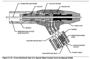
Water-cooled torches are designed for use at higher welding currents on a continuous duty cycle than similar sizes of gas-cooled torches. Typical welding currents of 300 to 500 amperes can be used, although some torches have been built to handle welding currents up to 1000amperes. Most machine or automatic welding applications use water-cooled torches.
Collets. Electrodes of various diameters are secured in the electrode holder by appropriately sized collets or chucks. Collets are typically made of a copper alloy. The electrode is gripped by the collet when the torch cap is tightened in place. Good contact between the electrode and the inside diameter of the collet is essential for proper current transfer and electrode cooling.
Nozzles. Shielding gas is directed to the weld zone by gas nozzles or cups which fit onto the head of the torch. Also incorporated in the torch body are diffusers, or carefully patterned jets, which feed the shield gas to the nozzle. Their purpose is to assist in producing a laminar flow of the exiting gas shield. Gas nozzles are made of various heat-resistant materials in different shapes, diameters, and lengths. These nozzles are either threaded to the torch or held by friction fit.
Nozzles are also available with elongated trailing sections or flared ends which provide better shielding for welding metals such as titanium, which is highly susceptible to contamination at elevated temperatures.
Gas Lenses. One device used for assuring a laminar flow of shielding gas is an attachment called a gas lens. Gas lenses contain a porous barrier diffuser and
are designed to fit inside the gas nozzle and around the electrode or collet. Gas lenses produce a longer, undisturbed flow of shielding gas. They enable operators to weld with the nozzle 25 mm (1 in.) or more from the work, improving their ability to see the weld pool and allowing them to reach places with limited access, such as inside comers.
Electrodes
In GTAW, the word tungsten refers to the pure element tungsten and its various alloys used as electrodes. Tungsten electrodes are nonconsumable if the process is properly used, because they do not melt or transfer to the weld. In other welding processes, such as SMAW, GMAW, and SAW, the elects-ode is the filler metal. The function of a tungsten electrode is to serve as one of the electrical terminals of the arc which supplies the heat required for welding. Its melting point is 3410°C (6170°F).Approaching this high temperature, tungsten becomes thermionic; it is a ready
source of electrons. It reaches this temperature by resistance heating and, were it not for the significant cooling effect of electrons boiling from its tip, resistance heating would cause the tip to melt. In fact, the electrode tip is much cooler than that part of the electrode between the tip and the externally-cooled collet.
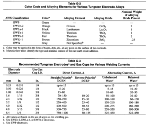
Classification of Electrodes .Tungsten electrodes are classified on the basis of the-ir chemical compositions, as specified in Table G-2. Requirements for tungsten electrodes are given in the latest edition of ANSUAWS A5.12, Specification for Tungsten and Tungsten Alloy Electrodes for Arc Welding and Cutting. The color code identification system for the various classes of tungsten electrodes is shown in Table G-2.
Electrodes are produced with either a clean finish or ground finish. Electrodes with a clean finish have been chemically cleaned to remove surface impurities after
the forming operation. Those with a ground finish have been centerless ground to remove surface imperfections.
Electrode Sizes and Current Capacities. Tungsten and tungsten alloy electrode sizes and current ranges are listed in Table G-3, along with shield-gas cup diameters recommended for use with different types of welding power. Table G-3 provides a useful guide for selecting the correct electrode for specific applications involving different current levels and power supplies.
Current levels in excess of those recommended for a given electrode size and tip configuration will cause the tungsten to erode or melt. Tungsten particles may
fall into the weld pool and become defects in the weld DCEN and DCEP. In general, it is about 50% less than joint. Current too low for a specific electrode diameter for a specific electrode diameter can cause arc instability.
Direct current with the electrode positive (DCEP) requires a much larger diameter to support a given level of current because the tip is not cooled by the evaporation of electrons but heated by their impact. In general, a given electrode diameter on DCEP would be expected to handle only 10% of the current possible with the electrode negative. With alternating current, the tip is cooled during the electrode negative cycle and heated when positive. Therefore, the current-carrying capacity of an electrode on ac is between that of requires a much larger diameter to support a given DCEN and DCEP. In general, it is about 50% less than that of DCEN.
EWP Electrode Classification. Pure tungsten electrodes (EWP) contain a minimum of 99.5% tungsten, with no intentional alloying elements. Pure tungsten electrodes are used mainly with ac for welding aluminum and magnesium alloys. The tip of the EWP electrode maintains a shiny, balled end, which provides good arc stability.
EWTh Electrode Classifications. The thermionic emission of tungsten can be improved by alloying it with metal oxides that have very low work functions. As a result, the electrodes are able to handle higher welding currents without failing. Thorium oxide is one such additive. To prevent identification problems with these and other types of tungsten electrodes, they are color coded as shown in Table G-2. Two types of thoriated tungsten electrodes are available. The EWTh- 1 and EWTh-2 electrodes contain 1% and 2% thorium oxide (ThO2) called thoria, respectively, evenly dispersed through their entire lengths. They were designed for DCEN applications. They are not often used with ac because it is difficult to maintain the balled end, which is necessary with ac welding, without splitting the electrode.
Thorium is a very low-level radioactive material. The level of radiation has not been found to represent a health hazard. However, if welding is to be performed in confined spaces for prolonged periods of time, or if electrode grinding dust might be ingested, special precautions relative to ventilation should be considered. The user should consult the appropriate safety personnel.
A discontinued classification of tungsten electrodes is the EWTh-3 class. This “striped” tungsten electrode had a longitudinal or axial segment which contained 1.0%to 2.0% thoria. The average thoria content of the electrode was 0.35% to 0.55%. Advances in powder metallurgy and other processing developments have caused this electrode classification to be discontinued, and it is no longer commercially available.
EWCe Electrode Classification. Ceriated tungsten electrodes were first introduced into the United States in the early 1980s.These electrodes were developed as possible replacements for thoriated electrodes because cerium, unlike thorium, is not a radioactive element. The EWCe-2 electrodes are tungsten electrodes containing 2% cerium oxide (CeO2), referred to as ceria. Compared with pure tungsten, the ceriated electrodes
exhibit a reduced rate of vaporization or burn-off. These advantages of ceria improve with increased ceria content. EWCe-2 electrodes will operate successfully with ac or dc.
EWLa Electrode Classification. EWLa-1 electrodes were developed around the same time as the ceriated electrodes and for the same reason: that lanthanum is not radioactive. These electrodes contain I % lanthanum oxide (La203), referred to as Zunthana. The
advantages and operating characteristics of these electrodes are very similar to the ceriated tungsten electrodes.
EWZr Electrode Classification. Zirconiated tungsten electrodes (EWZr) contain a small amount of zirconium oxide (ZrOz), as listed in Table G-2. Zirconiated tungsten electrodes have welding characteristics that generally fall between those of pure and thoriated tungsten. They are used for ac welding because they combine the desirable arc stability characteristics and balled end typical of pure tungsten with the current capacity and starting characteristics of thoriated tungsten. They have higher resistance to contamination than pure tungsten, and are preferred for radiographic quality welding applications where tungsten contamination of the weld must be minimized.
EWG Electrode Classification. The EWG electrode classification was assigned for alloys not covered by the above classes. These electrodes contain an unspecified addition of an unspecified oxide or combination of oxides (rare earth or others). The purpose of the addition is to affect the nature or characteristics of the arc, as defined by the manufacturer. The manufacturer must identify the specific addition or additions and the
nominal quantity or quantities added.
Several EWG electrodes are either commercially available or are being developed. These include additions of yttrium oxide or magnesium oxide. This classification also includes ceriated and lanthanated electrodes which contain these oxides in amounts other than as listed above, or in combination with other oxides.
Electrode Tip Configurations. The shape of the tungsten electrode tip is an important process variable in GTAW. Tungsten electrodes may be used with a variety of tip preparations. With ac welding, pure or zirconiated tungsten electrodes form a hemispherical balled end. For dc welding, thoriated, ceriated, or lanthanated tungsten electrodes are usually used. For the latter, the end is typically ground to a specific included angle, often with a truncated end.
Grinding. To produce optimum arc stability, grinding of tungsten electrodes should be done with the axis of the electrode perpendicular to the axis of the grinding wheel. The grinding wheel should be reserved for grinding only tungsten to eliminate possible contamination of the tungsten tip with foreign matter during the grinding operation. Exhaust hoods should be used when grinding thoriated electrodes to remove the grinding dust from the work area.
Wire Feeders
Wire feeders are used to add filler metal during automatic and machine welding. Either room temperature (cold) wire or preheated (hot) wire can be fed into the molten weld pool. Cold wire is fed into the leading edge and hot wire is fed into the trailing edge of the molten pool.
Cold Wire. The system for feeding of cold wire has three components: (1) wire drive mechanism, (2) speed control, and (3) wire guide attachment to introduce the wire into the molten weld pool.
The drive consists of a motor and gear train to power a set of drive rolls which push the wire. The control is essentially a constant-speed governor which can be either a mechanical or an electronic device. The wire is fed to the wire guide through a flexible conduit.
An adjustable wire guide is attached to the electrode holder. It maintains the position at which the wire enters the weld and the angle of approach relative to the electrode, work surface, and the joint. In heavy-duty applications, the wire guide is water cooled. Wires ranging from 0.4 to 2.4 mm (0.015 to 3/32 in.) in diameter are used. Special wire feeders are available to provide continuous, pulsed, or intermittent wire feed.
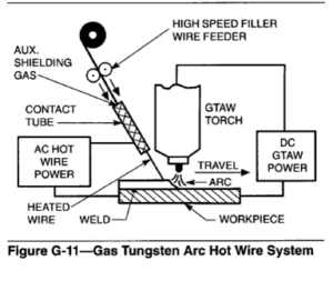
Hot Wire. The process for hot wire addition is similar to that for cold wire, except that the wire is resistance heated to a temperature close to its melting point just before it contacts the molten weld pool. When using a preheated (hot) wire in machine and automatic gas tungsten arc welding in the flat position, the wire is fed mechanically to the weld pool through a holder from which inert gas flows to protect the hot wire from oxidation. This system is illustrated in Figure G-11. Normally, a mixture of 75%helium-25% argon is used to shield the tungsten electrode and the molten weld pool.
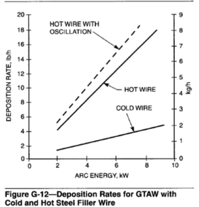
Deposition rate is greater with hot wire than with cold wire, as shown in Figure G-12. This rate is comparable to that in gas metal arc welding. The current flow is initiated when the wire contacts the weld surface. The wire is fed into the molten pool directly behind the arc at a 40 to 60o angle with respect to the tungsten electrode. The wire is resistance-heated by alternating current from a constant-voltage power source. Alternating current is used for heating the wire to avoid arc blow. When the heating current does not exceed 60% of the arc current, the arc oscillates 30o in the longitudinal direction. The oscillation increases to 120o when the heating and arc currents are equal. The amplitude of arc oscillation can be controlled by limiting the wire diameter to 1.2 mm (0.045 in.) and reducing the heating current below 60% of the arc current.
Preheated filler wire has been used successfully for joining carbon and low-alloy steels, stainless steels, and alloys of copper and nickel. Preheating is not recommended for aluminum and copper because the low resistance of these filler wires requires high heating current, which results in excessive arc deflection and uneven melting
Constant-current type power sources are used for GTAW. Power required for both a-c and d-c GTAW can be supplied by transformer-rectifier power supplies or from rotating a-c or d-c generators. Advances in semiconductor electronics have made transformer rectifier power sources popular for both shop and field GTAW, but rotating-type power sources continue to be widely used in the field.
GTAW power sources typically have either drooping or nearly true constant-current static output characteristics, such as those shown in Figure G-13. The static output characteristic is a function of the type of welding current control used in the power source design.
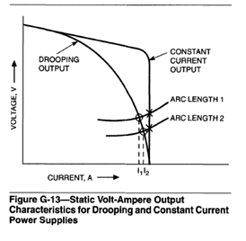
A drooping volt-ampere characteristic is typical of magnetically controlled power source designs including the moving coil, moving shunt, moving core reactor, saturable reactor, or magnetic amplifier designs and also rotating power source designs. A truly constant-current output is available from electronically controlled power sources. The drooping characteristic is advantageous for manual welding where a remote foot pedal current control is not available at the site of welding. With a drooping characteristic, the welder may vary the current level slightly by changing the arc length. The degree of current control possible by changing arc length can be inferred from Figure G-13.
In most of the magnetically controlled power sources, the current-level control is accomplished in the ac portion of the power source. As a result, these power sources are not typically used to provide pulsed current because of their slow dynamic response. The addition of a rectifier bridge allows these power sources to provide both a-c and d-c welding current. Those power sources which use a moving component for current control cannot readily be remotely controlled with a foot pedal, while the others typically can.
The advantages of magnetically controlled power sources are that they are simple to operate, require little maintenance in adverse industrial environments, and are relatively inexpensive. The disadvantages are that they are large in size and weight and have a lower efficiency compared to electronically controlled power sources. Also, most magnetic-control techniques are open-loop, which limits repeatability, accuracy, and response. An essentially constant-current volt-ampere characteristic can be provided by electronically controlled power sources, such as the series linear regulator, silicon controlled rectifier, secondary switcher, and inverter designs.
The advantages of electronically controlled power sources are that they offer rapid dynamic response, provide variable current waveform output, have excellent repeatability, and offer remote control. The disadvantages are that they are more complex to operate and maintain and are relatively expensive.
It is important to select a GTAW power source based on the type of welding current required for a particular application. The types of welding current include a-c sine-wave, a-c square-wave, dc, and pulsed dc. Many power sources are available with a variety of additional controls and functions such as water and shielding gas control, wire feeder and travel mechanism sequencing, current up-slope and down-slope, and multiple-current sequences.
Shielding Gases
Shielding gas is directed by the torch to the arc zone and weld pool to protect the electrode and the molten weld metal from atmospheric contamination. Backup purge gas can also be used to protect the underside of the weld and its adjacent base metal surfaces from oxidation during welding. Uniformity of root bead contour, freedom from undercutting, and the desired amount of root bead reinforcement are more likely to be achieved when using gas backup under controlled conditions. In some materials, gas backup reduces root cracking and porosity in the weld.
Types of Shielding Gases. Argon and helium, or mixtures of the two, are the most common types of inert gas used for shielding. Argon-hydrogen mixtures are used for special applications.
Argon. Welding grade argon is refined to a minimum purity of 99.95%. This is acceptable for GTAW of most metals except the reactive and refractory metals, for which a minimum purity of 99.997% is required. Often, such metals are fabricated in chambers from which all traces of air have been purged prior to initiating the welding operation.
Argon is used more extensively than helium because of the following advantages:
(1) Smoother, quieter arc action
(2) Reduced penetration
(3) Cleaning action when welding materials such as aluminum and magnesium
(4)Lower cost and greater availability
(5)Lower flow rates for good shielding
(6) Better cross-draft resistance
(7) Easier arc starting
The reduced penetration of an argon shielded arc is particularly helpful when manual welding of thin material, because the tendency for excessive melt-through is lessened. This same characteristic is advantageous in vertical or overhead welding, since the tendency for the base metal to sag or run is decreased.
Helium. Welding grade helium is refined to a purity of at least 99.99%.
For given values of welding current and arc length, helium transfers more heat into the work than argon. The greater heating power of the helium arc can be advantageous for joining metals of high thermal conductivity and for high-speed mechanized applications. Also, helium is used more often than argon for welding heavy plate. Mixtures of argon and helium are useful when some balance between the characteristics of both is desired.
Characteristics of Argon and Helium. The chief factor influencing shielding effectiveness is the gas density. Argon is approximately one and one-third times as heavy as air and ten times heavier than helium. Argon, after leaving the torch nozzle, forms a blanket over the weld area. Helium, because it is lighter, tends to rise around the nozzle. Experimental work has consistently shown that to produce equivalent shielding effectiveness, the flow of helium must be two to three times that of argon. The same general relationship is true for mixtures of argon and helium, particularly those high in helium content.
The other influential characteristic is that of arc stability. Both gases provide excellent stability with direct current power. With alternating current power, which is used extensively for welding aluminum and magnesium, argon provides much better arc stability and the highly desirable cleaning action, which makes argon superior to helium in this respect.
Argon-Hydrogen Mixtures. Argon-hydrogen mixtures are employed in special cases, such as mechanized welding of light-gauge stainless steel tubing, where the hydrogen does not cause adverse metallurgical effects such as porosity and hydrogen-induced
cracking. Increased welding speeds can be achieved in almost direct proportion to the amount of hydrogen added to argon because of the increased arc voltage. However, the amount of hydrogen that can be added varies with the metal thickness and type of joint for each particular application. Excessive hydrogen will cause porosity. Hydrogen concentrations up to 35% have been used on all thicknesses of stainless steel where a root opening of approximately 0.25 to 0.5 mm (0.010 to 0.020 in.) is used. Argon-hydrogen mixtures are limited to use on stainless steel, nickel-copper, and nickel-base alloys.
The general subject of safety and safe practices in welding, cutting, and allied processes is covered in ANSI 249.1, latest edition, Safety in Welding and Cutting. This publication is available from the American Welding Society. All welding personnel should be familiar with the safe practices discussed in this document.
The potential hazard areas in arc welding and cutting include, but are not limited to, the handling of cylinders and regulators, gases, fumes, radiant energy and electric shock.
Reference: American Welding Society, Welding Handbook, 8th Edition, Vol 2, Welding Processes. Miami, Florida: American Welding Society, 1991.
GAS TUNGSTEN ARC WELDING, Manual
Manual gas tungsten arc welding requires a fair degree of hand-eye coordination. It is necessary to keep the end of the filler metal inside the argon shield whenever it is hot enough to react with the atmosphere. If this is not done, the operator will bring the
oxidized end of the filler metal into the puddle, which results in contamination.
Manual Welding Procedure
Starting an Arc. To start an arc in alternating current welding, the electrode does not have to touch the workpiece. The superimposed high-frequency current jumps the gap between the welding electrode and the work, thus establishing a path for the welding current to follow. To strike an arc, the power supply is first turned on, and the torch held in a position about 2 in.
above the workpiece. Then the end of the torch is quickly swung down toward the workpiece, so that the end of the electrode is about 1/8 in. above the plate. The arc will then strike. This downward motion should be made rapidly to provide the maximum gas protection to the weld zone.
In direct current welding, the same torch motion is used for striking an arc. In this case, however, the electrode must touch the workpiece in order for the arc to strike. As soon as the arc is struck, the electrode should be withdrawn approximately 1/8 in. above the workpiece to avoid contaminating the electrode in the molten puddle.
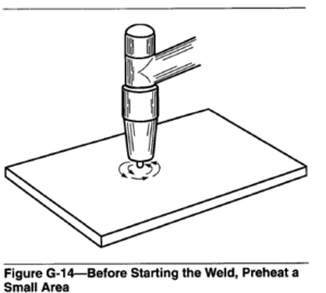
Making a Butt Weld. After the arc has been struck, the torch is held at about a 75″ angle to the surface of the workpiece. The starting point of the work is first preheated by moving the torch in small circles until a molten puddle is formed. (See Figure G-14). The end of the electrode should be held approximately 1/8 in. above the workpiece. When the puddle becomes bright and fluid, the torch should be moved slowly and steadily along the joint at a speed that will produce a bead of uniform width. No oscillation or other movement of the torch, except for the steady forward motion, is required.
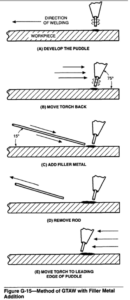
When filler metal is needed to provide reinforcement, the welding rod is held at about a 75″ angle to the work and about 1 in. away from the starting point. First the starting point is preheated, and the puddle developed as previously described. When the puddle becomes bright and fluid, the arc is moved to the rear of the puddle, and filler metal added by quickly touching the rod to the leading edge of the puddle. The rod is removed, and the arc brought back to the leading edge of the puddle. As soon as the puddle is again bright, the same steps are repeated. This sequence, continued for the
entire length of the seam, is illustrated in Figure G-15.
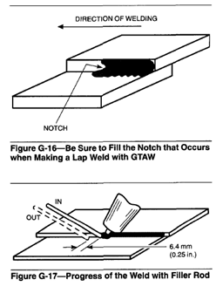
Making a Lap Weld. The first step of starting a lap weld or joint is developing a puddle on the bottom sheet. When the puddle becomes bright and fluid, the arc is shortened to about 1.6mm (1/16 in.). The torch is oscillated directly over the joint until the sheets are
firmly joined. Once the weld is started, the oscillating movement is no longer necessary. The torch is then moved along the seam with the end of the electrode just above the edge of the top sheet.
In lap welding, the puddle developed will be boomerang or V-shaped. The center of the puddle is called the “notch,” and the speed at which this notch travels will determine how fast the torch can be moved ahead. Care must be taken that this notch is completely filled in for the entire length of the seam. See Figure G-16. Otherwise, it is impossible to get 100 percent fusion and good penetration.
When filler metal is used, faster welding speeds are possible as the rod helps fill the notch. It is important to get complete fusion. Just laying in bits of filler rod on the cold, unfused base metal must be avoided. The rod should be alternately dipped into the puddle and withdrawn 1/4 in. or so, as illustrated in Figure G-17. By carefully controlling the melting rate of the top edge, and by adding just the right amount of filler metal where needed, a good uniform bead of proper proportions can be obtained.
Making a Corner or Edge Joint. This is the easiest type of weld to make. A puddle is developed at the starting point, and the torch moved straight along the joint. Travel speed is regulated to produce a uniform looking bead. Too slow a welding speed will cause molten metal to roll off the edge. Irregular or too high speeds will produce a rough, uneven surface. No filler metal is required.