In structures or systems where service stresses are high, such as in heavy machinery, ship and building construction, extensive framework and intricate angles
may include miles or more of welded joints. Shearing stresses can affect a large percentage of the total system of welds. Correct design of a fillet weld on angles
implies an optimum balance between the effective weld length and the contact area between the weld and either base metal part.
A sound engineering approach is mandatory, and allowable shearing stresses must be accurately calculated to specify weld sizes and length which will result in the most economical application of strength, joint efficiency, and safety in service.
In dealing with angles, the welded joints must be proportioned correctly and designed to reduce internal stresses and strains which often cause buckling, distortion, and ultimate failure. These stresses are due to the differential expansion occurring with the heating or cooling of a weld.
When designing a fillet weld, weldability must be a consideration. A careful investigation must include individual welding conditions, e.g., design of the workpiece or structure, section thickness, accessibility, service requirements, and manufacturing cost. It is essential to consider the size instead of the throat of a fillet weld.
In fillet welds in which the cross section is an equal isosceles right triangle, the throat is equal to the product of the size and sine 45o:
T = L sine 45o = 0.707L.
Any weld metal outside the triangle limits is omitted in estimating weld strength, so
the material between the dashed line and the curved surface of the weld is considered extraneous and disregarded. The convexity of a fillet weld should be reduced, since a 45″ flat fillet is the most desirable shape for weld performance. For equivalent strength
and rigidity, long fillet welds with smaller leg sizes are the most economical.
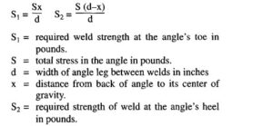
When the stress in an angle is transmitted entirely by welds along the toe and heel of the angle, the required weld strength may be calculated as follows:
According to the recommendations of AWS D1.l, Structural Welding Code-Steel, and the American Institute of Steel Construction for steel in buildings, the allowable shearing unit stress of a section through the throat of a fillet weld is 94 MPa (13 600 psi). This stress is to be used in conjunction with structural steel ASTM A-7, which is for structural steel having an ultimate tensile strength between 414 and 483 (60 000
and 70 000 psi). The factor of safety (about 4) applicable to building construction has been applied to the working stress.
The required area of contact of a weld in a building problem, for example, may be determined by the following:
0.707 x 13 600 = 9600
F_
DL= 9600
where D is the weld size; L is the effective weld length in inches; and F is the resultant shearing force on the weld in pounds.